System Generator是Xilinx公司进行数字信号处理开发的一种设计工具,它通过将Xilinx开发的一些模块嵌入到Simulink的库中,可以在Simulink中进行定点仿真,可以设置定点信号的类型,这样就可以比较定点仿真与浮点仿真的区别。并且可以生成HDL文件,或者网表,可以在ISE中进行调用。或者直接生成比特流下载文件。能够加快DSP系统的开发进度。
一、Black Box调用HDL代码
1、简介
System Generator提供了一个特性:可以通过black box这个block将其它HDL文件以黑盒的形式封装到System Generator设计中,在仿真时使用Simulink+Vivado Simulator(或ModelSim)协同仿真的方法,在Simulink环境中完成设计的仿真测试。
具体介绍大家可以查阅相关资料。
2、本部分设计使用到的block
Xilinx block
其它block
3、System Generator设计流程
3.1 HDL建模
使用HDL代码实现该滤波器,本设计这里使用Xilinx公司提供的一个转置型FIR滤波器设计文件,采用VHDL实现。顶层文件transpose_fir_vhd代码清单如下:
library IEEE;
use IEEE.STD_LOGIC_1164.ALL;
use IEEE.STD_LOGIC_ARITH.ALL;
use IEEE.STD_LOGIC_SIGNED.ALL;
-- Uncomment the following lines to use the declarations that are
-- provided for instantiating Xilinx primitive components.
--library UNISIM;
--use UNISIM.VComponents.all;
entity transpose_fir is
Port ( din : in std_logic_vector(11 downto 0);
clk : in std_logic;
ce : in std_logic;
rst : in std_logic_vector(0 downto 0);
dout : out std_logic_vector(25 downto 0));
end transpose_fir;
architecture Behavioral of transpose_fir is
component mac
generic (
coef_value : integer := 0
);
port(
din : in std_logic_vector(11 downto 0);
cin : in std_logic_vector(25 downto 0);
clk : in std_logic;
ce : in std_logic;
rst : in std_logic;
dout : out std_logic_vector(25 downto 0));
end component;
constant N : integer := 23; -- Number of Coefficients
type coef_array is array (0 to N-1) of integer; -- Coefficient Values
constant coefficient : coef_array := (-38, -74, -109, -109, -37, 140, 435, 827, 1262, 1663, 1945, 2047, 1945, 1663, 1262, 827, 435, 140, -37, -109, -109, -74, -38);
signal cin_temp : std_logic_vector(26*N downto 0) := CONV_STD_LOGIC_VECTOR (0, 26*N+1);
begin
G0: for I in 0 to N-1 generate
G_first: if I = 0 generate
M0: MAC
generic map (
coef_value => coefficient(I)
)
port map (
din => din,
cin => "00000000000000000000000000",
clk => clk,
ce => ce,
rst => rst(0),
dout => cin_temp(25 downto 0));
end generate;
GX: if (I >= 1 and I < N-1) generate
M1: MAC
generic map (
coef_value => coefficient(I)
)
port map (
din => din,
cin => cin_temp(I*25+(I-1) downto ((I-1)*26)),
clk => clk,
ce => ce,
rst => rst(0),
dout => cin_temp((I+1)*25+I downto I*26));
end generate;
G_last: if I = N-1 generate
M2: MAC
generic map(
coef_value => coefficient(I)
)
port map (
din => din,
cin => cin_temp(I*25+(I-1) downto ((I-1)*26)),
clk => clk,
ce => ce,
rst => rst(0),
dout => dout);
end generate;
end generate;
end Behavioral;
其中调用的乘累加MAC单元mac.vhd的代码清单如下:
library IEEE;
use IEEE.STD_LOGIC_1164.ALL;
use IEEE.STD_LOGIC_ARITH.ALL;
use IEEE.STD_LOGIC_SIGNED.ALL;
-- Uncomment the following lines to use the declarations that are
-- provided for instantiating Xilinx primitive components.
--library UNISIM;
--use UNISIM.VComponents.all;
entity mac is
generic(
coef_value : integer := 0
);
port(
din : in std_logic_vector(11 downto 0);
cin : in std_logic_vector(25 downto 0);
clk : in std_logic;
ce : in std_logic;
rst : in std_logic;
dout : out std_logic_vector(25 downto 0));
end mac;
architecture Behavioral of mac is
signal coef : std_logic_vector(11 downto 0);
signal product : std_logic_vector(23 downto 0);
signal addition : std_logic_vector(25 downto 0);
begin
coef <= CONV_STD_LOGIC_VECTOR (coef_value, 12);
--sign extend the coefficients
-- Multiplication
process(clk, ce, din, coef)
begin
if clk'event and clk='1' then
if (ce='1') then
product <= din * coef;
end if;
end if;
end process;
-- Addition chain
addition <= product + cin;
-- Register result
process(clk, ce, addition, rst)
begin
if (rst = '0') then
dout <= "00000000000000000000000000";
elsif (clk'event and clk='1') then
if (ce='1') then
dout <= addition;
end if;
end if;
end process;
end Behavioral;
3.2 建立Model
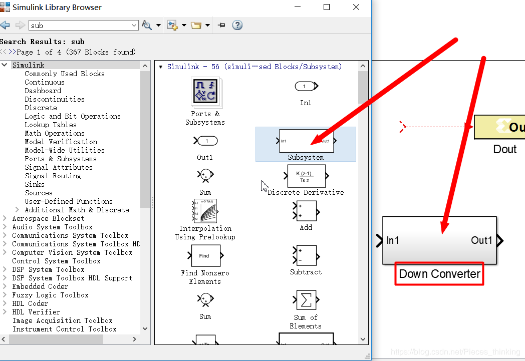
添加subsystem 命名 Down Converter
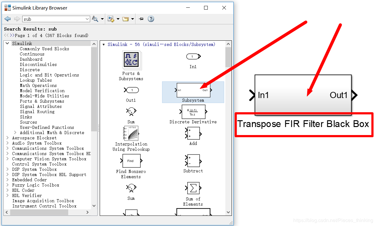
添加subsystem 命名 Transpose FIR Filter Black Box
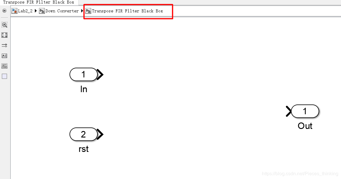
在Transpose FIR Filter Black Box subsystem 添加two input ports and one output port
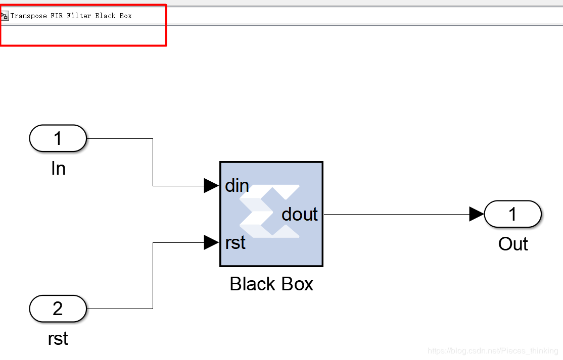
将两个VHDL文件放在slx文件所在路径下。添加一个Black Box到subsystem中,会自动弹出一个窗口,选择transpose_fir.vhd文件。初始化完毕后,软件会自动生成一个transpose_fir_config.m的MATLAB配置文件,这个文件与设置的VHDL文件相对应,配置了HDL文件在Simulink环境中的具体信息。
关闭后,Black Box会根据MATLAB配置文件中的内容,自动更新block的管脚信息。有人会注意到:VHDL中定义了时钟信号clk和时钟使能信号ce,然而在Black Box上确没有显示。这是因为时钟信号clk、时钟使能信号ce会被特殊对待,在System Generator中会用设置的Simulink采样率来驱动时钟信号。

双击打开该block:

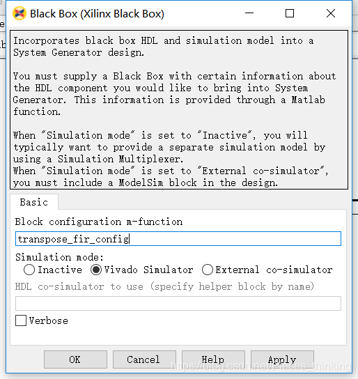
“Block configuration m-function”显示了与该block绑定的MATLAB配置文件。由于HDL文件不能直接在Simulink进行仿真,需要配置协同仿真模式,可选的Simulaion mode有三种:
当使用其它协同仿真工具时,还需要添加其它的block来搭建仿真源。这里为了方便,选择使用“Vivado Simulator”来仿真HDL模型。
按照下列方式进行连接后,CLOSE
在 Down Converter subsystem 添加如下Block:

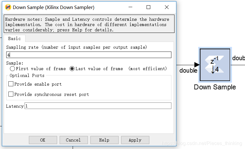


添加完上诉Block,CLOSE
整个Model如下:

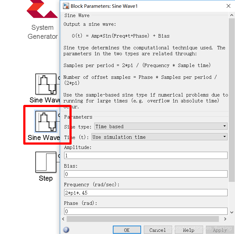
相关Block设置如下:


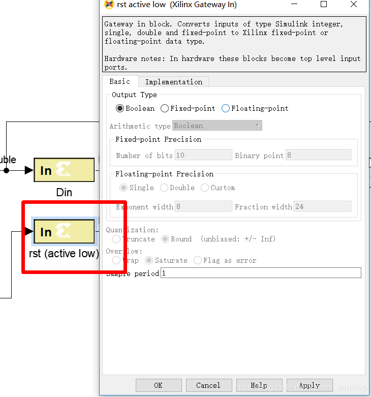
产生一个阶跃信号作为VHDL的复位信号rst。HDL代码中设计为低电平有效复位,因此这里设置“Initial value”为0,“Finial value”为1,“Step time”设置为5/20e6,即维持5个系统时钟周期的复位状态。
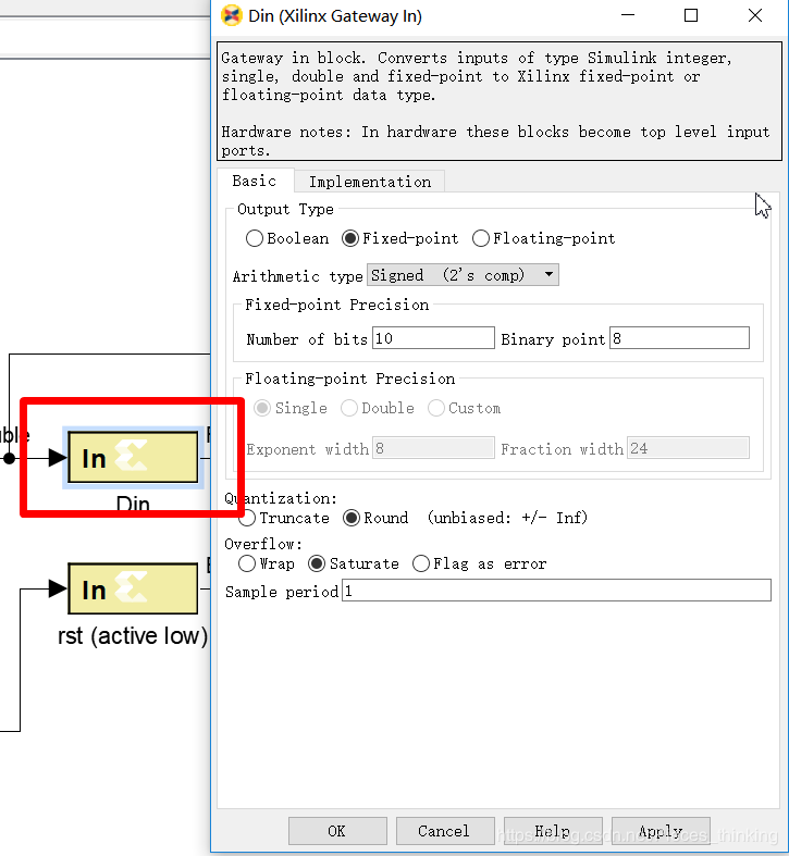
再添加一个Gateway In block,设置20Mhz采样率,复位信号为单比特,因此数据类型设置为Boolean。输入信号的Gateway In block数据格式改为Fix_12_10,与VHDL模型对应。
3.3 修改MATLAB配置文件
系统自动生成的MATLAB配置文件只包含了软件能读取到的信息,其它信息还需我们自己设置。本设计需要修改以下两点:
VHDL设计中采用的是带符号定点数,因此将第26行的 “dout_port.setType(‘UFix_26_0’);”改为“dout_port.setType(‘Fix_26_23’);”,否则在Simulink环境中用示波器无法正确显示block的输出。

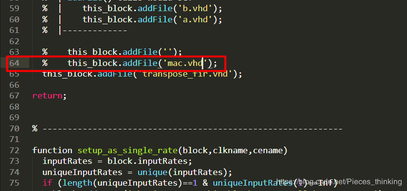
该block只关联了transpose_fir.vhd文件,而该文件还调用了子模块mac.vhd文件。在第64行将注释改为“this_block.addFile(‘mac.vhd’);”,添加该文件,否则仿真时不能正确运行。
3.4 运行仿真
运行仿真,仿真时间设置为“500”
可以看到经过滤波后,9MHz频率分量的信号有明显衰减。示波器波形如下:
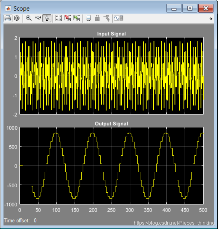
明显看到1MHz+9Mhz的叠加信号经过滤波后只剩下1Mhz的正弦波。
关于Black Box的具体特性即MATLAB配置文件的更多内容可以参考ug958文档。
4、Black Box及配置文件详解
摘自:https://blog.csdn.net/FPGADesigner/article/details/80982814
4.1 HDL文件使用限制
想在Black Box中导入HDL文件,Verilog/VHDL文件必须遵循以下限制:
4.2 MATLAB配置文件
将需要导入的VHDL/Verilog文件放在slx文件所在目录下。添加一个Black Box到model中,会自动弹出一个窗口,选择好需要关联的HDL文件。初始化完毕后,软件会自动生成一个name_config.m的MATLAB配置文件(name为HDL文件名称),这个文件与设置的HDL文件相对应,配置了HDL文件在Simulink环境中的具体信息。
通常这个M文件不修改也可以使用,当HDL设计比较复杂时还是需要手工修改(如上部分的设计),因此了解该配置文件仍有必要。下表给出了配置文件中的关键语句及对应信息:
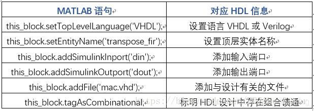
上表中的“组合馈通”(combinational feed-through)指的是输入没有经过任何寄存器直接到达输出(即路径上只存在组合逻辑)。当HDL设计中存在这样的路径时,必须使用上表中语句申明。
为了保证Black Box在Simulink中能够正确运行,MATLAB配置文件中还包含以下三个部分。
4.2.1 输出端口设置
软件是无法检测到我们如何规定输出端口的某些信息的,因此这部分必须我们手工设定,如下:
dout_port = this_block.port('dout');
dout_port.setType('Fix_26_23');
dout_port.setRate(theInputRate);
上面将输出端口速率设置与输入端口速率不同。如果输出端口速率为输入端口速率的2倍,则可以设置为:“dout_port.setRate(2*theInputRate);”。这部分设置主要是让Simulink可以正确的从Black Box中获取输出结果,保证仿真正确运行。
4.2.2 输入类型检查
检测该block的输入数据类型是否正确,如不正确则提示相关信息(如这里HDL中din为12Bits数据,此处检测向block输入的数据是否为12Bits):
if (this_block.inputTypesKnown)
if (this_block.port('din').width ~= 12);
this_block.setError('Input data type for port "din" must have width=12.');
end
end
4.2.3 输入速率检查
以下语句便是完成了时钟信号速率的设置,setup_as_single_rate函数中读取了Simulink环境设置的系统采样率,如果采样率设置正确,则会用该速率驱动时钟信号clk:
if (this_block.inputRatesKnown)
setup_as_single_rate(this_block,'clk','ce')
end
setup_as_single_rate这个函数内容比较多,这里不再赘述。读者可以按照本系列第11篇的设计进行,打开相应的MATLAB文件查看。
4.3 block参数设置
Black Box的参数设置界面如下:
“Block confituration m-function”设置了MATLAB配置文件,该文件一般与slx模型文件在同一目录下。编辑框中不能包含后缀“.m”。
“Simulation mode”设置仿真时所选用的模式:
需要添加对应ModelSim block,且在“HDL co-simulator to use”中标明block名称。
---------------------
作者:碎碎思
来源:CSDN
原文:https://blog.csdn.net/Pieces_thinking/article/details/83693011