作者:bt(CSDN)
本文使用工程源码已上传https://download.csdn.net/download/botao_li/10891304
从本文档开始将介绍PS和PL之间通过AXI总线互联。
三种AXI总线协议为
① AXI_LITE:性能较低的地址映射传输,一次只能传输4字节
② AXI_STREAM:高速流数据传输,无地址映射,不能直接与PS连接
③ AXI(又称AXI_FULL):性能较高的地址映射传输
AXI_LITE一般用于小规模的数据交互,比如参数、指令或者状态信息
本文档用AXI_LITE总线实现2项功能:
① PS读写PL的寄存器读取板上按钮状态控制LED灯开关
② PL读写PS的DDR内存
axi lite时序
下文中生成的AXI_LITE接口的IP模块自带的示例代码可以修改后使用,AXI_LITE的接口时序来源于示例代码的参考
写操作时序
master:同时设置awvalid和wvalid有效
slave:等待awvalid和wvalid同时有效,同时将awready和wready设置1
slave:在awvalid awready wvalid wready同时为1的情况下,bvalid设1,同时取出awaddr和wdata
master:收到awready将awvalid设0,收到wready将wvalid设0
master:收到bvalid将bready设1,下个时钟周期设0
slave:收到bready将bvalid设0
读操作时序
master:设置arvalidy为1
slave:收到arvalid将arready设1,下个时钟周期设0
slave:在arready arvalid同时为1的情况下,rvalid设1,axi_rresp设0有效
master:收到arready将arvalid设0
master:收到rvalid将rready设1,下个时钟周期设0
slave:收到rready将rvalid设1
master:在rready rvalid同时为1的情况下,检查rdata数值
建立工程
与之前相同的方法建立zcu102的Vivado工程
配置Zynq模块
建立Block Design,并添加Zynq模块
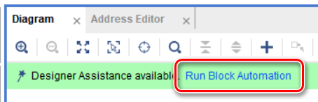
选择Run Block Automation
在弹出窗口中按照默认配置选择OK
双击打开Zynq模块配置,在PS-PL Configuration页进行如下配置
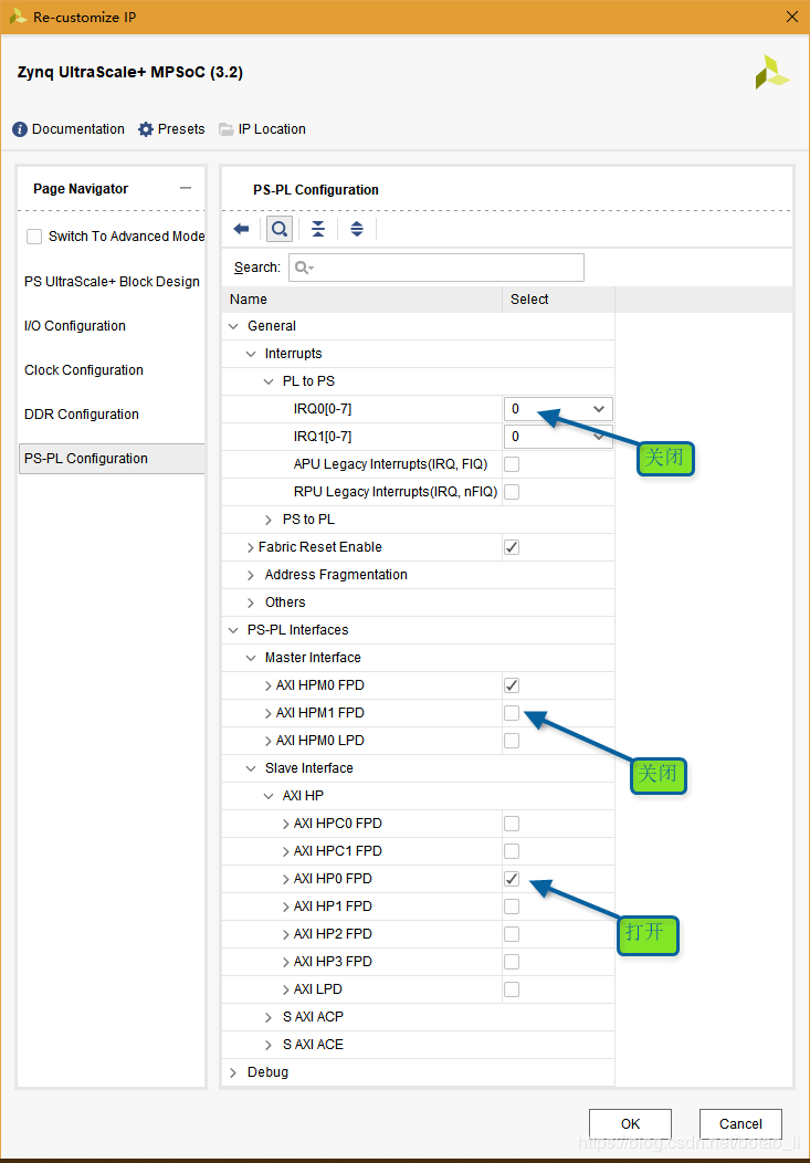
使用pl_clk0作为PL端工作时钟,并且连接2个AXI接口的aclk

自定义Slave AXI_LITE接口的IP模块
在Tools菜单选择Create and Package New IP
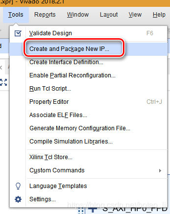
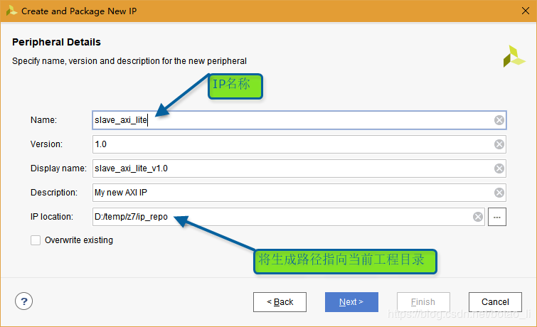
在弹出窗口中选中Create AXI4 Peripheral

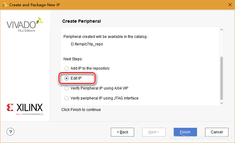
选择Edit IP后点击Finish
之后弹出当前IP的Vivado工程
在Sources窗口双击打开接口模块

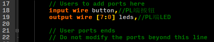
在代码注释中指示的位置**(非必须)**添加自定义的模块端口
注意:端口定义必须加上wire

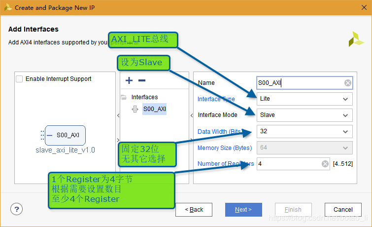
根据代码所示,前述步骤配置的4个32位寄存器分别为slv_reg0~3
若当前IP在PS端的基地址为base_addr,则slv_reg0读写地址为base_addr,slv_reg1读写地址为base_addr+4,svl_reg2和3以此类推
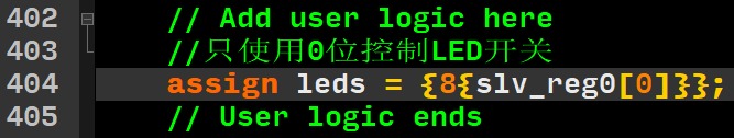
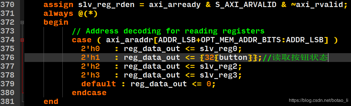
将slv_reg0用于写入PL端LED,slv_reg1用于读取PL端按钮
根据注释位置(位置非必须)添加以下代码
并修改读操作赋值
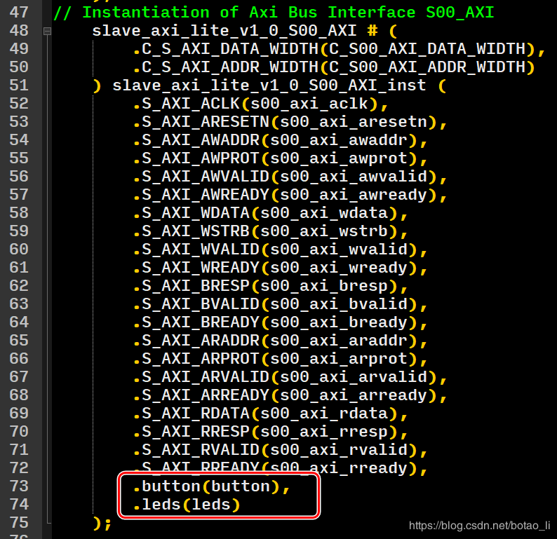
打开IP的顶层模块,进行如下修改

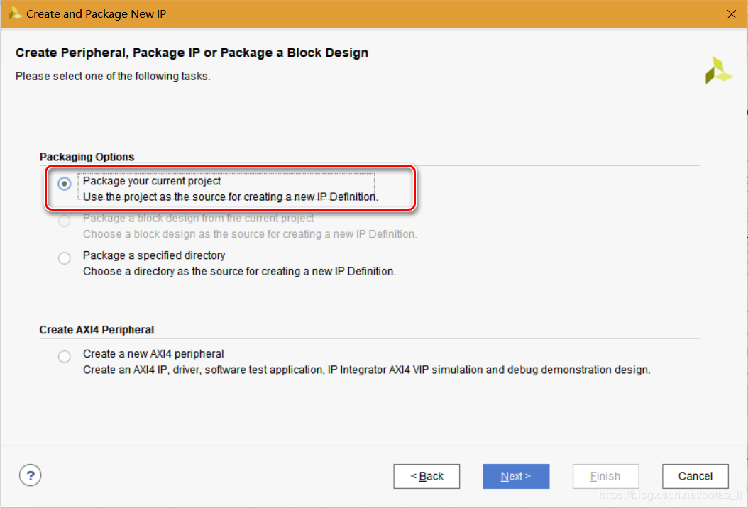
在当前IP的Vivado工程界面,在Tools菜单选择Create and Package IP
选择Package your current project
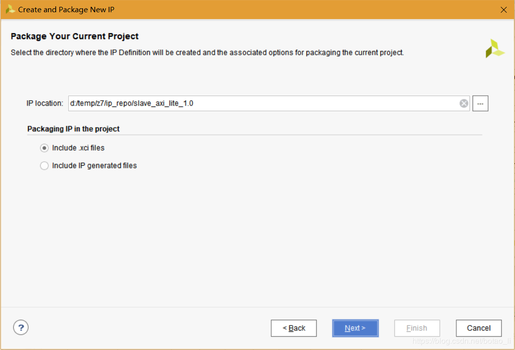
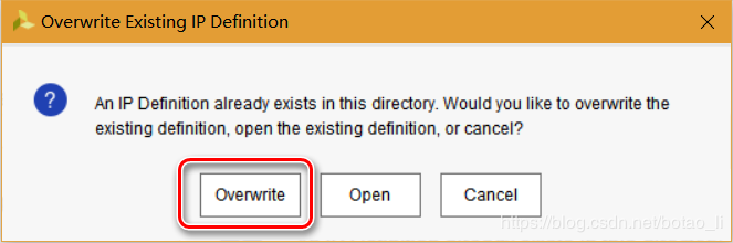
在弹出窗口选择Overwrite
最后点击Finish
完成后关闭当前IP的Vivado工程
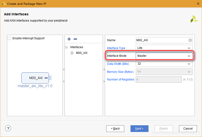
自定义Master AXI_LITE接口的IP模块
参考[Slave AXI_LITE的模块的生成](#自定义Slave AXI_LITE接口的IP模块),进行如下配置
最后选择Edit IP打开IP的Vivado工程
由于默认生成的示例代码过于复杂,因此根据AXI_LITE接口时序全部重写,并添加读写接口
进入Vivado工程后,使用与[自定义Slave接口IP相同的方式](#自定义Slave AXI_LITE接口的IP模块)修改接口模块和顶层模块如下
接口模块代码
顶层模块代码
最后,参考[Slave AXI_LITE的模块的生成](#自定义Slave AXI_LITE接口的IP模块),打包IP
建立Verilog的master端测试模块
在Sources窗口创建新verilog模块,命名为master_test.v,用于连接master_axi_lite的读写接口进行测试
代码如下:
实现Vivado工程
回到之前建立的Zynq工程
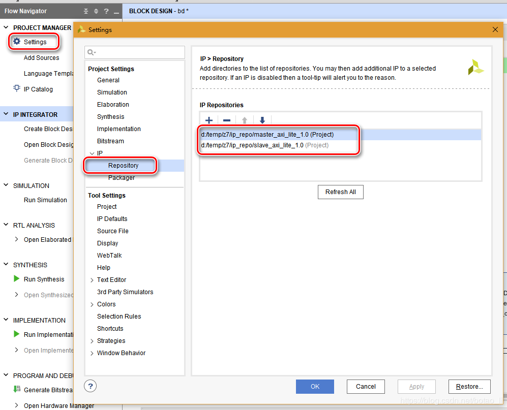
在PROJECT MANAGER内打开Settings,在IP > Repository页确认前述2个IP的路径已添加
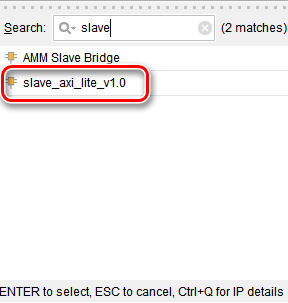
向Block Design中添加2个自定义的AXI_LITE模块

之后从Sources窗口将master_test.v文件用鼠标拖动至Diagram窗口,自动生成master_test的模块
在Block Design点击Run Connection Automation
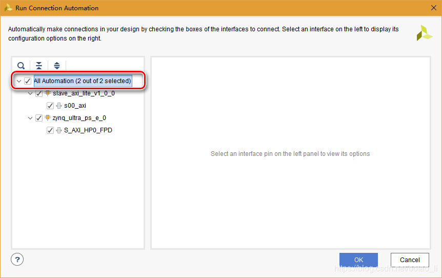
点击OK后,Block Design完成自动连接
之后手动连接master_test与master_axi_lite模块的接口
完成连接后的Diagram如下:

在Block Design上右键菜单执行Generate Output Products,完成后在右键菜单执行Create HDL Wrapper
在Flow Navigator中Run Synthesis,完成后,打开Synthesized Design,从Layout菜单打开I/O Planning窗口设置button和leds管脚
保存并新建xdc约束文件top.xdc
接下来在Flow Navigator中SYNTHESIS下选择Set Up Debug,添加master_test中的测试信号
最终的top.xdc文件内容如下:
set_property PACKAGE_PIN AG14 [get_ports {leds_0[0]}]
set_property PACKAGE_PIN AF13 [get_ports {leds_0[1]}]
set_property PACKAGE_PIN AE13 [get_ports {leds_0[2]}]
set_property PACKAGE_PIN AJ14 [get_ports {leds_0[3]}]
set_property PACKAGE_PIN AJ15 [get_ports {leds_0[4]}]
set_property PACKAGE_PIN AH13 [get_ports {leds_0[5]}]
set_property PACKAGE_PIN AH14 [get_ports {leds_0[6]}]
set_property PACKAGE_PIN AL12 [get_ports {leds_0[7]}]
set_property IOSTANDARD LVCMOS33 [get_ports {leds_0[7]}]
set_property IOSTANDARD LVCMOS33 [get_ports {leds_0[6]}]
set_property IOSTANDARD LVCMOS33 [get_ports {leds_0[5]}]
set_property IOSTANDARD LVCMOS33 [get_ports {leds_0[4]}]
set_property IOSTANDARD LVCMOS33 [get_ports {leds_0[3]}]
set_property IOSTANDARD LVCMOS33 [get_ports {leds_0[1]}]
set_property IOSTANDARD LVCMOS33 [get_ports {leds_0[0]}]
set_property IOSTANDARD LVCMOS33 [get_ports {leds_0[2]}]
set_property PACKAGE_PIN AF15 [get_ports button_0]
set_property IOSTANDARD LVCMOS33 [get_ports button_0]

create_debug_core u_ila_0 ila
set_property ALL_PROBE_SAME_MU true [get_debug_cores u_ila_0]
set_property ALL_PROBE_SAME_MU_CNT 1 [get_debug_cores u_ila_0]
set_property C_ADV_TRIGGER false [get_debug_cores u_ila_0]
set_property C_DATA_DEPTH 2048 [get_debug_cores u_ila_0]
set_property C_EN_STRG_QUAL false [get_debug_cores u_ila_0]
set_property C_INPUT_PIPE_STAGES 0 [get_debug_cores u_ila_0]
set_property C_TRIGIN_EN false [get_debug_cores u_ila_0]
set_property C_TRIGOUT_EN false [get_debug_cores u_ila_0]
set_property port_width 1 [get_debug_ports u_ila_0/clk]
connect_debug_port u_ila_0/clk [get_nets [list bd_i/zynq_ultra_ps_e_0/inst/pl_clk0]]
set_property PROBE_TYPE DATA_AND_TRIGGER [get_debug_ports u_ila_0/probe0]
set_property port_width 32 [get_debug_ports u_ila_0/probe0]
connect_debug_port u_ila_0/probe0 [get_nets [list {bd_i/master_test_0/rd_data[0]} {bd_i/master_test_0/rd_data[1]} {bd_i/master_test_0/rd_data[2]} {bd_i/master_test_0/rd_data[3]} {bd_i/master_test_0/rd_data[4]} {bd_i/master_test_0/rd_data[5]} {bd_i/master_test_0/rd_data[6]} {bd_i/master_test_0/rd_data[7]} {bd_i/master_test_0/rd_data[8]} {bd_i/master_test_0/rd_data[9]} {bd_i/master_test_0/rd_data[10]} {bd_i/master_test_0/rd_data[11]} {bd_i/master_test_0/rd_data[12]} {bd_i/master_test_0/rd_data[13]} {bd_i/master_test_0/rd_data[14]} {bd_i/master_test_0/rd_data[15]} {bd_i/master_test_0/rd_data[16]} {bd_i/master_test_0/rd_data[17]} {bd_i/master_test_0/rd_data[18]} {bd_i/master_test_0/rd_data[19]} {bd_i/master_test_0/rd_data[20]} {bd_i/master_test_0/rd_data[21]} {bd_i/master_test_0/rd_data[22]} {bd_i/master_test_0/rd_data[23]} {bd_i/master_test_0/rd_data[24]} {bd_i/master_test_0/rd_data[25]} {bd_i/master_test_0/rd_data[26]} {bd_i/master_test_0/rd_data[27]} {bd_i/master_test_0/rd_data[28]} {bd_i/master_test_0/rd_data[29]} {bd_i/master_test_0/rd_data[30]} {bd_i/master_test_0/rd_data[31]}]]
create_debug_port u_ila_0 probe
set_property PROBE_TYPE DATA_AND_TRIGGER [get_debug_ports u_ila_0/probe1]
set_property port_width 32 [get_debug_ports u_ila_0/probe1]
connect_debug_port u_ila_0/probe1 [get_nets [list {bd_i/master_test_0/rd_addr[0]} {bd_i/master_test_0/rd_addr[1]} {bd_i/master_test_0/rd_addr[2]} {bd_i/master_test_0/rd_addr[3]} {bd_i/master_test_0/rd_addr[4]} {bd_i/master_test_0/rd_addr[5]} {bd_i/master_test_0/rd_addr[6]} {bd_i/master_test_0/rd_addr[7]} {bd_i/master_test_0/rd_addr[8]} {bd_i/master_test_0/rd_addr[9]} {bd_i/master_test_0/rd_addr[10]} {bd_i/master_test_0/rd_addr[11]} {bd_i/master_test_0/rd_addr[12]} {bd_i/master_test_0/rd_addr[13]} {bd_i/master_test_0/rd_addr[14]} {bd_i/master_test_0/rd_addr[15]} {bd_i/master_test_0/rd_addr[16]} {bd_i/master_test_0/rd_addr[17]} {bd_i/master_test_0/rd_addr[18]} {bd_i/master_test_0/rd_addr[19]} {bd_i/master_test_0/rd_addr[20]} {bd_i/master_test_0/rd_addr[21]} {bd_i/master_test_0/rd_addr[22]} {bd_i/master_test_0/rd_addr[23]} {bd_i/master_test_0/rd_addr[24]} {bd_i/master_test_0/rd_addr[25]} {bd_i/master_test_0/rd_addr[26]} {bd_i/master_test_0/rd_addr[27]} {bd_i/master_test_0/rd_addr[28]} {bd_i/master_test_0/rd_addr[29]} {bd_i/master_test_0/rd_addr[30]} {bd_i/master_test_0/rd_addr[31]}]]
create_debug_port u_ila_0 probe
set_property PROBE_TYPE DATA_AND_TRIGGER [get_debug_ports u_ila_0/probe2]
set_property port_width 32 [get_debug_ports u_ila_0/probe2]
connect_debug_port u_ila_0/probe2 [get_nets [list {bd_i/master_test_0/wr_addr[0]} {bd_i/master_test_0/wr_addr[1]} {bd_i/master_test_0/wr_addr[2]} {bd_i/master_test_0/wr_addr[3]} {bd_i/master_test_0/wr_addr[4]} {bd_i/master_test_0/wr_addr[5]} {bd_i/master_test_0/wr_addr[6]} {bd_i/master_test_0/wr_addr[7]} {bd_i/master_test_0/wr_addr[8]} {bd_i/master_test_0/wr_addr[9]} {bd_i/master_test_0/wr_addr[10]} {bd_i/master_test_0/wr_addr[11]} {bd_i/master_test_0/wr_addr[12]} {bd_i/master_test_0/wr_addr[13]} {bd_i/master_test_0/wr_addr[14]} {bd_i/master_test_0/wr_addr[15]} {bd_i/master_test_0/wr_addr[16]} {bd_i/master_test_0/wr_addr[17]} {bd_i/master_test_0/wr_addr[18]} {bd_i/master_test_0/wr_addr[19]} {bd_i/master_test_0/wr_addr[20]} {bd_i/master_test_0/wr_addr[21]} {bd_i/master_test_0/wr_addr[22]} {bd_i/master_test_0/wr_addr[23]} {bd_i/master_test_0/wr_addr[24]} {bd_i/master_test_0/wr_addr[25]} {bd_i/master_test_0/wr_addr[26]} {bd_i/master_test_0/wr_addr[27]} {bd_i/master_test_0/wr_addr[28]} {bd_i/master_test_0/wr_addr[29]} {bd_i/master_test_0/wr_addr[30]} {bd_i/master_test_0/wr_addr[31]}]]
create_debug_port u_ila_0 probe
set_property PROBE_TYPE DATA_AND_TRIGGER [get_debug_ports u_ila_0/probe3]
set_property port_width 32 [get_debug_ports u_ila_0/probe3]
connect_debug_port u_ila_0/probe3 [get_nets [list {bd_i/master_test_0/wr_data[0]} {bd_i/master_test_0/wr_data[1]} {bd_i/master_test_0/wr_data[2]} {bd_i/master_test_0/wr_data[3]} {bd_i/master_test_0/wr_data[4]} {bd_i/master_test_0/wr_data[5]} {bd_i/master_test_0/wr_data[6]} {bd_i/master_test_0/wr_data[7]} {bd_i/master_test_0/wr_data[8]} {bd_i/master_test_0/wr_data[9]} {bd_i/master_test_0/wr_data[10]} {bd_i/master_test_0/wr_data[11]} {bd_i/master_test_0/wr_data[12]} {bd_i/master_test_0/wr_data[13]} {bd_i/master_test_0/wr_data[14]} {bd_i/master_test_0/wr_data[15]} {bd_i/master_test_0/wr_data[16]} {bd_i/master_test_0/wr_data[17]} {bd_i/master_test_0/wr_data[18]} {bd_i/master_test_0/wr_data[19]} {bd_i/master_test_0/wr_data[20]} {bd_i/master_test_0/wr_data[21]} {bd_i/master_test_0/wr_data[22]} {bd_i/master_test_0/wr_data[23]} {bd_i/master_test_0/wr_data[24]} {bd_i/master_test_0/wr_data[25]} {bd_i/master_test_0/wr_data[26]} {bd_i/master_test_0/wr_data[27]} {bd_i/master_test_0/wr_data[28]} {bd_i/master_test_0/wr_data[29]} {bd_i/master_test_0/wr_data[30]} {bd_i/master_test_0/wr_data[31]}]]
create_debug_port u_ila_0 probe
set_property PROBE_TYPE DATA_AND_TRIGGER [get_debug_ports u_ila_0/probe4]
set_property port_width 1 [get_debug_ports u_ila_0/probe4]
connect_debug_port u_ila_0/probe4 [get_nets [list bd_i/master_test_0/rd_done]]
create_debug_port u_ila_0 probe
set_property PROBE_TYPE DATA_AND_TRIGGER [get_debug_ports u_ila_0/probe5]
set_property port_width 1 [get_debug_ports u_ila_0/probe5]
connect_debug_port u_ila_0/probe5 [get_nets [list bd_i/master_test_0/rd_en]]
create_debug_port u_ila_0 probe
set_property PROBE_TYPE DATA_AND_TRIGGER [get_debug_ports u_ila_0/probe6]
set_property port_width 1 [get_debug_ports u_ila_0/probe6]
connect_debug_port u_ila_0/probe6 [get_nets [list bd_i/master_test_0/rd_valid]]
create_debug_port u_ila_0 probe
set_property PROBE_TYPE DATA_AND_TRIGGER [get_debug_ports u_ila_0/probe7]
set_property port_width 1 [get_debug_ports u_ila_0/probe7]
connect_debug_port u_ila_0/probe7 [get_nets [list bd_i/master_test_0/wr_done]]
create_debug_port u_ila_0 probe
set_property PROBE_TYPE DATA_AND_TRIGGER [get_debug_ports u_ila_0/probe8]
set_property port_width 1 [get_debug_ports u_ila_0/probe8]
connect_debug_port u_ila_0/probe8 [get_nets [list bd_i/master_test_0/wr_en]]
set_property C_CLK_INPUT_FREQ_HZ 300000000 [get_debug_cores dbg_hub]
set_property C_ENABLE_CLK_DIVIDER false [get_debug_cores dbg_hub]
set_property C_USER_SCAN_CHAIN 1 [get_debug_cores dbg_hub]
connect_debug_port dbg_hub/clk [get_nets u_ila_0_pl_clk0]
在Flow Navigator中PROGRAM AND DEBUG选择Generate Bitstream
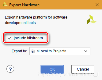
完成后在File菜单选择Export > Export Hardware,注意选中Include bitstream
之后在File菜单选择Launch SDK
SDK编程
默认建立的bd_wrapper_hw_platform_0工程目录中已包含前文生成的bit配置文件
根据HelloWorld模板建立test_axi_lite工程
SDK工程用于测试slave_axi_lite,即按钮控制led开关
修改helloworld.c文件代码如下:
在test_axi_lite工程选择Debug Configurations

配置如下:
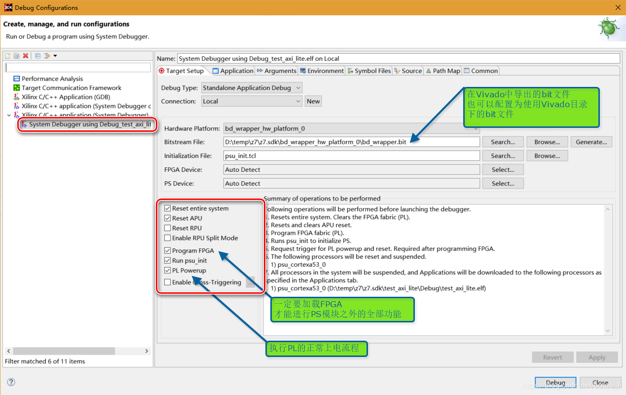
注意,一定不能在Vivado中加载FPGA,再启动PS程序。PL程序会在PS载入过程中被清除!!!
在SDK中启动调试
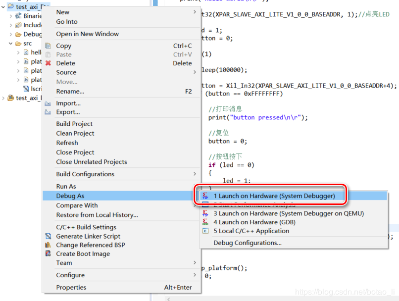
发现按钮控制led开关功能正确
回到Vivado,从Hardware Manager进入Debugl界面,测试发现master_test运行正确:

版权声明:本文为CSDN博主「bt_」的原创文章,遵循 CC 4.0 BY-SA 版权协议,转载请附上原文出处链接及本声明。
原文链接:https://blog.csdn.net/botao_li/article/details/85630090