作者:没落骑士
原文链接: https://www.cnblogs.com/moluoqishi/p/12358509.html
一、前言
Xlinx的ZYNQ系列SOC集成了APU、各种专用外设资源和传统的FPGA逻辑,为ARM+FPGA的应用提供助力,降低功耗和硬件设计难度的同时极大提高两者间传输的带宽。之前在研究生课题中使用过ZYNQ搭建环路系统对算法进行板级验证,但并没有深入使用和理解这个异构平台,今天算是对入门的总结。一款SOC的入门必然是GPIO的使用,而中断则是MCU能保证实时性的必杀武器。硬件调试难度高一直是FPGA的痛点,集成ARM的FPGA更是如此,cross-trigger调试有效地解决了这一问题,所以它也作为入门ZYNQ的必要技能。
二、硬件系统搭建
ZYNQ的三种GPIO分别是MIO、EMIO和AXI-GPIO。PS部分直接连接到芯片引脚的IO叫MIO,经过FPGA再连接到引脚的是EMIO。EMIO可以通过硬件约束指定不同的端口号和电压标准,提高了ARM IO的灵活性。而AXI-GPIO相当于是对ARM IO的补充,通过调用AXI-GPIO IP核与外部通信。以下通过一个实例来说明三种IO的使用方式。
系统功能:使用一个MIO使连接其上的LED闪烁,使用8个EMIO同样与LED连接构成流水灯效果,另外再调用一个5bit位宽的AXI-GPIO IP核以终端模式响应电路板上5个按键。
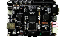
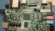
平台:米联客 MIZ702N (ZYNQ-7020)
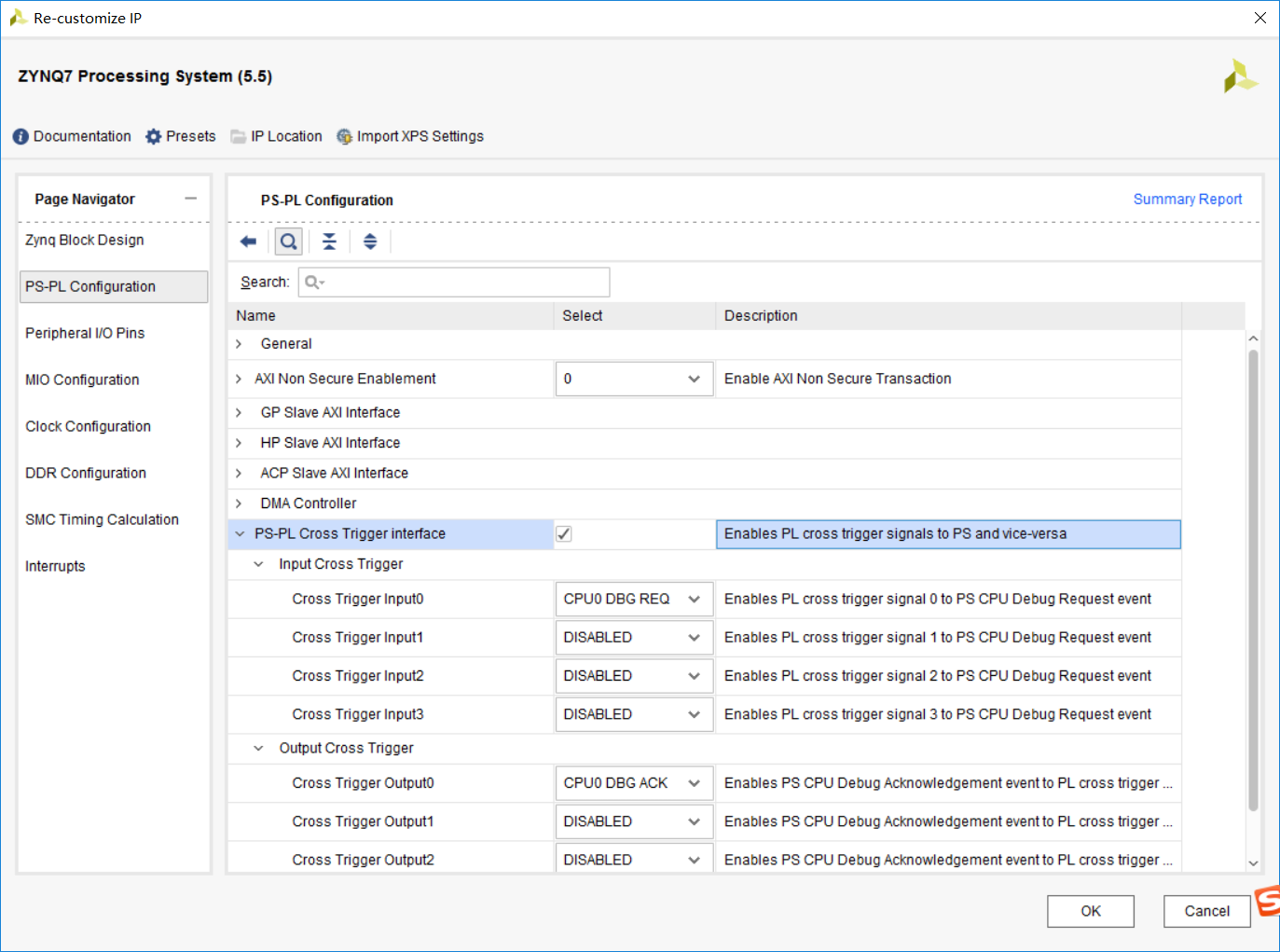
配置ZYNQ IP,使能MIO和EMIO,配置EMIO位宽是8bit。

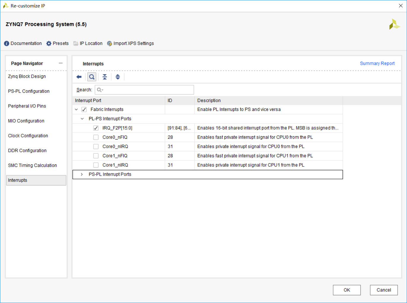
使能Cross Trigger和共享中断。
之后添加AXI-GPIO IP Core,配置位宽并使能其中断功能:

运行Run Automatic Connection最终block design系统结构:
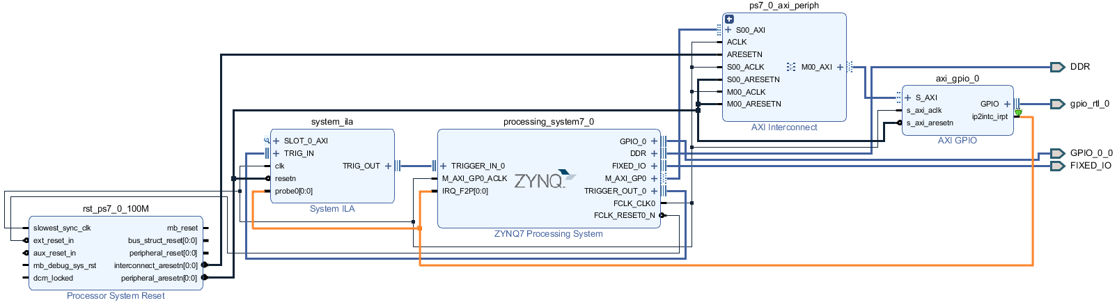
这里使用ILA抓取AXI-GPIO的中断信号。
三、软件编程与AXI-GPIO中断模式解析
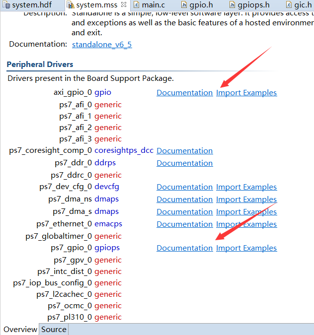
Implementation,export hardware with bitstream, launch SDK. BSP中自带了硬件系统所使用到的IP的一些示例代码和文档,为入门提供了很好的帮助。
为了方便复用,对Xilinx提供的API做进一步封装,生成gpiops.h gpiops.c gpio.h gpio.c和gic.h文件。接下来重点讲述GIC相关的代码原理。若要使用中断系统,首先要初始化GIC,和其他IP一样包括查找配置和初始赋值两个步骤,分别由LookupConfig和CfgInitialize两个函数完成。后者实际上初始化了中断处理句柄使其指向了一个空结构。要理解内部原理,需要弄清楚XScuGic的数据结构。
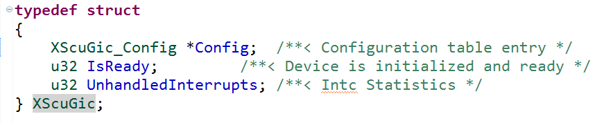

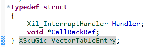
其中Handler实际上是一个函数指针类型,用于定义中断产生时的回调函数。而CallBackRef用于传入InstancePtr,即Gic Instance Pointer。GIC初始化完,要将GIC与中断ID和自定义中断回调函数绑定。
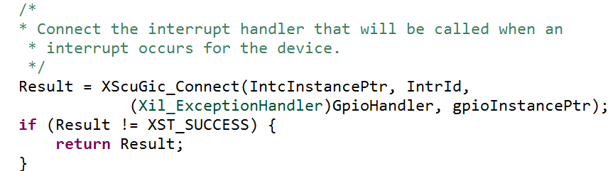
内部的核心代码依然和初始化时一致,只不过换成了输入参数:

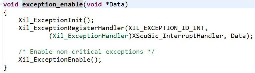
下一步该使能中断了,一方面是使用GIC对GPIO中断ID的响应,另一方面是使能AXI-GPIO的中断信号。最后是系统对异常的处理函数,这里将其封装在exception_enable中:
总结来看,中断系统建立的步骤为:
1 初始化GIC
2 连接GIC与中断ID和回调函数
3 使能中断
4 使能异常处理
那么为什么完成上述操作后,中断事件发生会立即执行自定义中断回调函数GpioHandler呢?CPU会将中断向量表存储在特定的寄存器中,读取该寄存器可以获取中断向量表内容,里边存放着各个中断ID对应的中断函数入口地址。跳转指令则有中断控制器完成。
接下来是各个文件的软件代码:
/*
* main.c
*
* Created on: 2020年2月22日
* Author: s
*/
#include "xparameters.h"
#include "xstatus.h"
#include
#include "sleep.h"
#include "gpiops.h"
#include "gpio.h"
#include "gic.h"
XGpioPs GpioPs; /* The driver instance for GPIO Device. */
XGpio Gpio;
XScuGic Intc; /* The Instance of the Interrupt Controller Driver */
#define printf xil_printf /* Smalller foot-print printf */
#define LOOP_NUM 8
static u32 MIO_OUT_PIN_INDEX =7; /* LED button */
static u32 EMIO_OUT_PIN_BASE_INDEX = 54;
volatile u32 IntrFlag; /* Interrupt Handler Flag */
void GpioHandler(void *CallbackRef);
int setupIntSystem(XScuGic *IntcInstancePtr,XGpio *gpioInstancePtr
,u32 IntrId);
int main()
{
int Status;
u8 i=0;
u32 sys_led_out=0x1;
Status = gpiops_initialize(&GpioPs,GPIOPS_DEVICE_ID);
if (Status != XST_SUCCESS) {
return XST_FAILURE;
}
Status = gpio_initialize(&Gpio,GPIO_DEVICE_ID);
if (Status != XST_SUCCESS) {
return XST_FAILURE;
}
/*
* Set the direction for the pin to be output and
* Enable the Output enable for the LED Pin.
*/
gpiops_setOutput(&GpioPs,MIO_OUT_PIN_INDEX);
for(i=0;i
}
gpio_setDirect(&Gpio, 1,GPIO_CHANNEL1);
Status = setupIntSystem(&Intc,&Gpio,INTC_GPIO_INTERRUPT_ID);
if (Status != XST_SUCCESS) {
return XST_FAILURE;
}
printf("Initialization finish.\n");
while(1){
for(i=0;i
gpiops_outputValue(&GpioPs, EMIO_OUT_PIN_BASE_INDEX+i, 0x1);
usleep(200*1000);
gpiops_outputValue(&GpioPs, EMIO_OUT_PIN_BASE_INDEX+i, 0x0);
}
gpiops_outputValue(&GpioPs, MIO_OUT_PIN_INDEX, sys_led_out);
sys_led_out = sys_led_out == 0x0 ? 0x1 : 0x0;
}
return 0;
}
int setupIntSystem(XScuGic *IntcInstancePtr,XGpio *gpioInstancePtr
,u32 IntrId)
{
int Result;
/*
* Initialize the interrupt controller driver so that it is ready to
* use.
*/
Result = gic_initialize(&Intc,INTC_DEVICE_ID);
if (Result != XST_SUCCESS) {
return XST_FAILURE;
}
XScuGic_SetPriorityTriggerType(IntcInstancePtr, IntrId,
0xA0, 0x3);
/*
* Connect the interrupt handler that will be called when an
* interrupt occurs for the device.
*/
Result = XScuGic_Connect(IntcInstancePtr, IntrId,
(Xil_ExceptionHandler)GpioHandler, gpioInstancePtr);
if (Result != XST_SUCCESS) {
return Result;
}
/* Enable the interrupt for the GPIO device.*/
XScuGic_Enable(IntcInstancePtr, IntrId);
/*
* Enable the GPIO channel interrupts so that push button can be
* detected and enable interrupts for the GPIO device
*/
XGpio_InterruptEnable(gpioInstancePtr,GPIO_CHANNEL1);
XGpio_InterruptGlobalEnable(gpioInstancePtr);
/*
* Initialize the exception table and register the interrupt
* controller handler with the exception table
*/
exception_enable(&Intc);
IntrFlag = 0;
return XST_SUCCESS;
}
void GpioHandler(void *CallbackRef)
{
XGpio *GpioPtr = (XGpio *)CallbackRef;
u32 gpio_inputValue;
/* Clear the Interrupt */
XGpio_InterruptClear(GpioPtr, GPIO_CHANNEL1);
printf("Input interrupt routine.\n");
//IntrFlag = 1;
gpio_inputValue = gpio_readValue(GpioPtr, 1);
switch(gpio_inputValue)
{
case 30:
printf("button up\n");
break;
case 29:
printf("button center\n");
break;
case 27:
printf("button left\n");
break;
case 23:
printf("button right\n");
break;
case 15:
print("button down\n");
break;
}
}
main.c
/*
* gpio.h
*
* Created on: 2020年2月23日
* Author: s
*/
#ifndef SRC_GPIO_H_
#define SRC_GPIO_H_
#include "xgpio.h"
#define GPIO_DEVICE_ID XPAR_GPIO_0_DEVICE_ID
#define INTC_GPIO_INTERRUPT_ID XPAR_FABRIC_AXI_GPIO_0_IP2INTC_IRPT_INTR
#define GPIO_CHANNEL1 0x1F
int gpio_initialize(XGpio * InstancePtr, u16 DeviceId);
void gpio_setDirect(XGpio *InstancePtr, unsigned Channel,
u32 DirectionMask);
void gpio_outputValue(XGpio * InstancePtr, unsigned Channel, u32 Data);
u32 gpio_readValue(XGpio * InstancePtr, unsigned Channel);
#endif /* SRC_GPIO_H_ */
gpio.h
/*
* gpio.c
*
* Created on: 2020年2月23日
* Author: s
*/
#include "gpio.h"
int gpio_initialize(XGpio * InstancePtr, u16 DeviceId)
{
return XGpio_Initialize(InstancePtr,DeviceId);
}
void gpio_setDirect(XGpio *InstancePtr, unsigned Channel,
u32 DirectionMask)
{
XGpio_SetDataDirection(InstancePtr, Channel,
DirectionMask);
}
void gpio_outputValue(XGpio * InstancePtr, unsigned Channel, u32 Data)
{
XGpio_DiscreteWrite(InstancePtr, Channel, Data);
}
u32 gpio_readValue(XGpio * InstancePtr, unsigned Channel)
{
return XGpio_DiscreteRead(InstancePtr, Channel);
}
gpio.c
/*
* gpiops.c
*
* Created on: 2020年2月23日
* Author: s
*/
#include "gpiops.h"
int gpiops_initialize(XGpioPs *InstancePtr,u16 DeviceId)
{
XGpioPs_Config *ConfigPtr;
ConfigPtr = XGpioPs_LookupConfig(DeviceId);
return XGpioPs_CfgInitialize(InstancePtr, ConfigPtr,
ConfigPtr->BaseAddr);
}
void gpiops_setOutput (XGpioPs *InstancePtr,u32 Pin)
{
XGpioPs_SetDirectionPin(InstancePtr, Pin, 1);
XGpioPs_SetOutputEnablePin(InstancePtr, Pin, 1);
}
void gpiops_setInput(XGpioPs *InstancePtr,u32 Pin)
{
XGpioPs_SetDirectionPin(InstancePtr, Pin, 0);
}
void gpiops_outputValue(XGpioPs *InstancePtr,u32 Pin,u32 Data)
{
XGpioPs_WritePin(InstancePtr, Pin, Data);
}
u32 gpiops_readValue(XGpioPs *InstancePtr,u32 Pin)
{
/* Read the state of the data so that it can be verified. */
return XGpioPs_ReadPin(InstancePtr, Pin);
}
gpiops.c
/*
* gpio.h
*
* Created on: 2020年2月23日
* Author: s
*/
#ifndef SRC_GPIOPS_H_
#define SRC_GPIOPS_H_
#include "xgpiops.h"
#define GPIOPS_DEVICE_ID XPAR_XGPIOPS_0_DEVICE_ID
int gpiops_initialize(XGpioPs *InstancePtr,u16 DeviceId);
void gpiops_setOutput (XGpioPs *InstancePtr,u32 Pin);
void gpiops_setInput(XGpioPs *InstancePtr,u32 Pin);
void gpiops_outputValue(XGpioPs *InstancePtr,u32 Pin,u32 Data);
u32 gpiops_readValue(XGpioPs *InstancePtr,u32 Pin);
#endif /* SRC_GPIOPS_H_ */
gpiops.h
/*
* gic.h
*
* Created on: 2020年2月23日
* Author: s
*/
#ifndef SRC_GIC_H_
#define SRC_GIC_H_
#include "xscugic.h"
#define INTC_DEVICE_ID XPAR_SCUGIC_SINGLE_DEVICE_ID
s32 gic_initialize(XScuGic *InstancePtr,u16 DeviceId)
{
XScuGic_Config *IntcConfig;
IntcConfig = XScuGic_LookupConfig(DeviceId);
if (NULL == IntcConfig) {
return XST_FAILURE;
}
return XScuGic_CfgInitialize(InstancePtr, IntcConfig,
IntcConfig->CpuBaseAddress);
}
void exception_enable(void *Data)
{
Xil_ExceptionInit();
Xil_ExceptionRegisterHandler(XIL_EXCEPTION_ID_INT,
(Xil_ExceptionHandler)XScuGic_InterruptHandler, Data);
/* Enable non-critical exceptions */
Xil_ExceptionEnable();
}
#endif /* SRC_GIC_H_ */
gic.h
四、交叉触发调试
右键工程文件夹->Run As/Debug As分别用于代码下载和调试。SDK基于GDB提供了强大的调试能力,支持断点运行,可查看内部寄存器、地址数值以及汇编代码等。Debug As ->Debug Configuartion,双击System Debugger新建ELF文件。勾选Reset entire system和Program FPGA,因为ELF只是软件,硬件信息存储在bitstream中。最重要的是勾选enable cross-triggering。

点击enable cross-triggering右侧的按钮,按照如下操作使能Processor to Fabric Trigger.
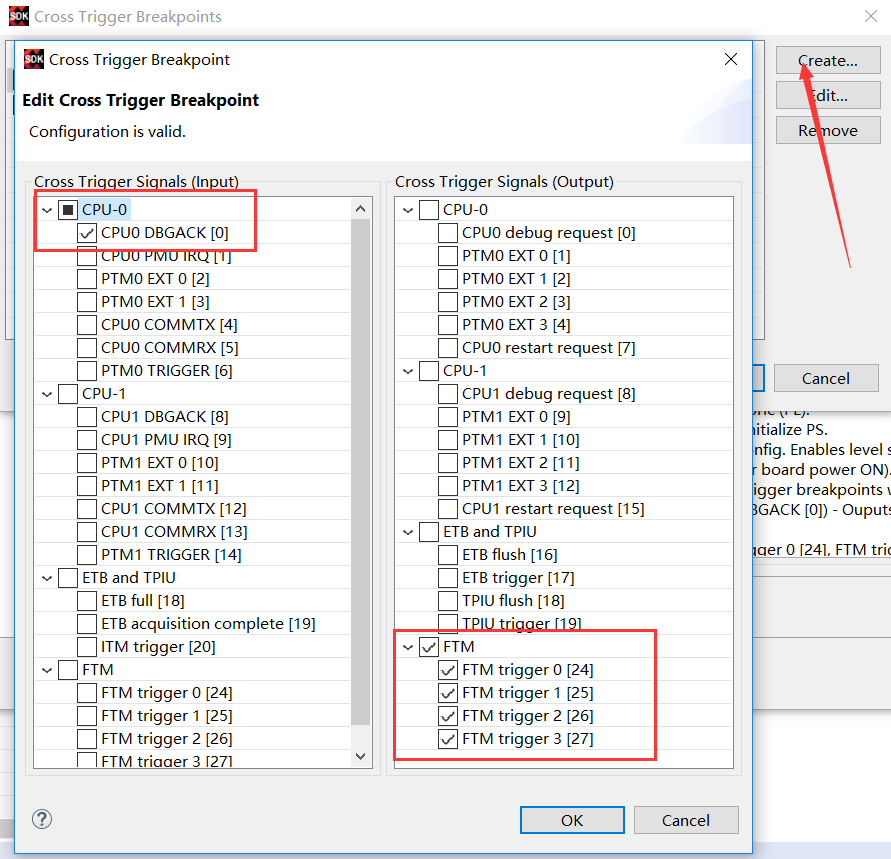
再次create使能Fabric to Processor Trigger:

最后点击Debug下载软硬件代码并进入调试界面。
1 首先尝试PS触发PL调试:
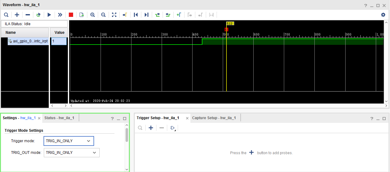
指定中断回调函数起始位置一个断点。然后进入VIVADO,打开Hardware Manager连接硬件。注意此时触发模式选择IN_ONLY。此时不用设置ILA抓取信号的触发条件,因为触发由PS端的PC控制。点击Run Trigger等待触发条件。这时回到SDK点击Resume按钮使代码开始运行。按下任意按键产生中断,此时软件代码运行到断点处停止,ILA随即抓取中断信号。
2 尝试PL触发PS调试:
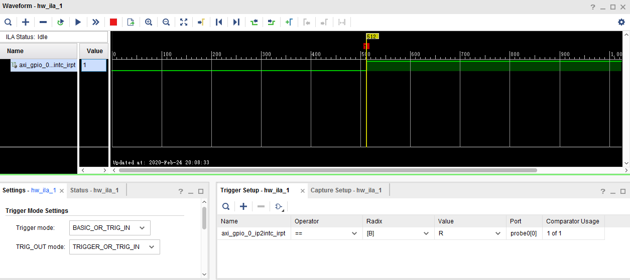
这回在VIVADO中设置触发模式为OR_TRIG_IN,并启动触发条件为上升沿触发。按下按键,C运行到满足ILA触发条件时C代码立即停止,故PL控制了PS端的程序运行。
可以看到此时程序进入IRQHandler。
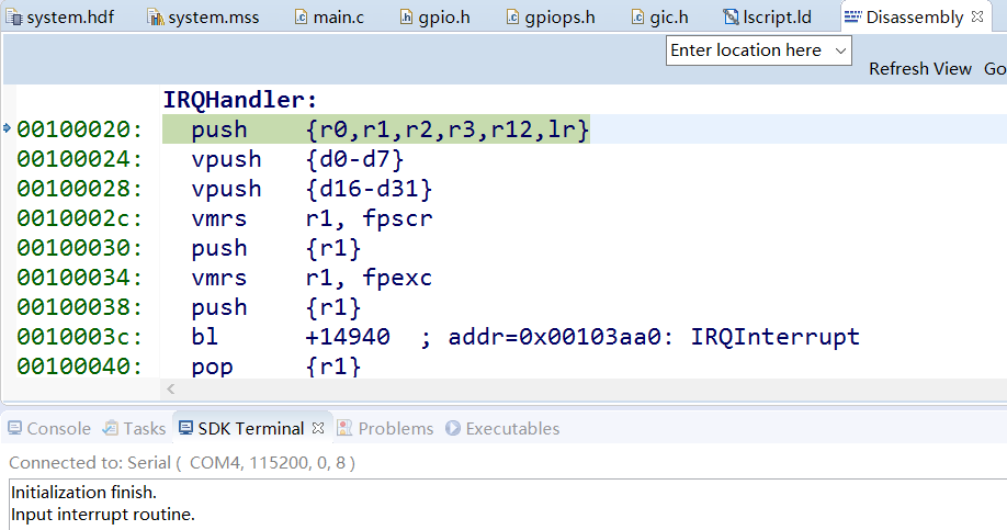
串口终端也打印进入中断函数的信息,正确响应中断。到此示例结束。本文虽是对ZYNQ入门的整理,但涉及到的东西很多,包括GPIO应用、中断系统建立和相应机制、调用AXI总线IP核、软件设计以及软硬件交叉触发调试流程。