作者: 碎碎思,本文转载自: OpenFPGA微信公众号
介绍
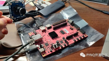
FPGA 的一大优势是我们可以实现并行图像处理数据流。虽然任务比较重,但是我们不需要昂贵的 FPGA,我们可以使用成本低廉范围中的一个,例如 Spartan 7 或 Artix 7。对于这个项目,将展示如何设计一个简单的图像处理应用程序,该应用程序平行处理两个摄像头。
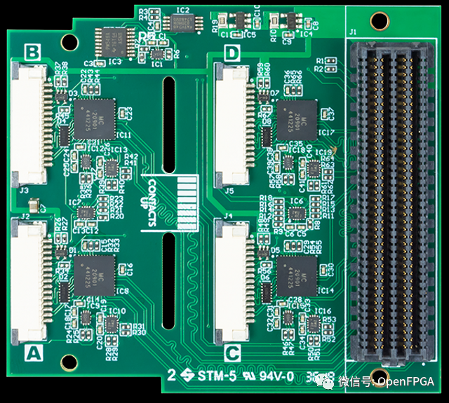
本项目主要使用 Digilent PCAM 扩展板。PCAM 扩展板为最多四个 PCAMS 提供接口。所以只需要有FMC接口的开发板都可以完成本项目移植。
Vivado
为了让系统快速启动和运行,我们将从赛灵思的一个示例项目开始设计。要打开参考项目,我们需要首先创建一个针对自己开发板上 FPGA 的项目。

打开项目后,创建一个新的BD。

打开BD后,在BD中添加一个 MIPI CSI2 IP。
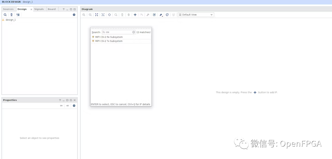
要打开参考设计,右键单击 CSI2 IP并选择打开 IP 示例设计。

我们将使用这个参考项目。首先要做的是移除 DSI 输出路径。这将为我们的图像处理平台释放 FPGA 中的逻辑资源。
下一步是添加以下元素以创建第二条图像处理通道。
CSI2 IP Block
Register Slices & concatenation
Sensor Demosaic
VDMA
AXI Switch
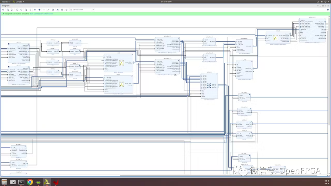
完成的设计应如下所示:

除了 CSI2 IP 中的设置外,第二个图像处理通道与第一个相同。
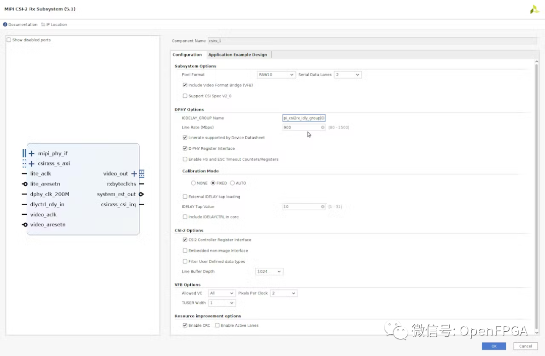
原始 CSI2 IP 设置

添加的 CSI2 IP 中的设置
VDMA 内存设置

Sensor Demosaic设置

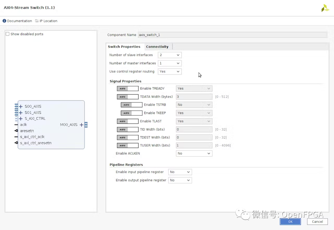
AXI4 Stream Switch
时钟有不同的上行和下行时钟


完成BD设计接下来就是针对硬件进行管脚约束。
一旦完成,我们就可以生成和构建项目并导出 XSA 用于软件开发。
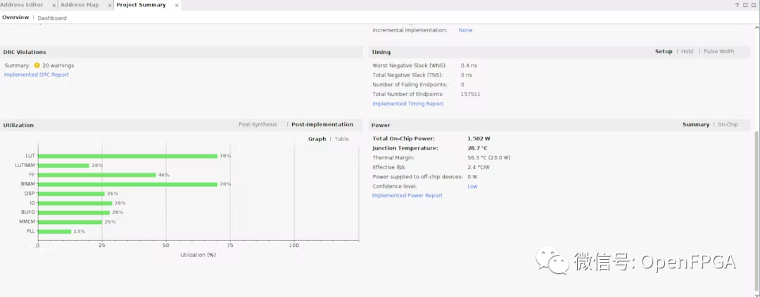
该设备的利用率如下:
软件开发
导出 XSA 后,我们可以创建一个新的 Vitis 项目,其中包含 hello world 应用程序。
从 hello world 应用程序 BSP 设置中,我们可以导入 MIPI CSI2 示例项目。

我们需要对这个项目进行一些更改。
首先是通过 IIC 与传感器通信并设置传感器。板上的 CSI2 Sensor与FPGA 的 I2C 并没有直接连接。通过一个I2C BUFFER,与四个sensor连接,因为sensor的地址是一样的。
这可以在 fucntion_prototpye.c 中提供的传感器配置函数中进行更改。
所以我们在配置运行之前需要选择多路复用器。
extern int SensorPreConfig(int pcam5c_mode) {
u32 Index, MaxIndex, MaxIndex1, MaxIndex2;
int Status;
SensorIicAddr = SENSOR_ADDRESS;
u8 SP701mux_addr = 0x75;
u8 SP701mux_ch = 0x40;
u8 PCAM_FMC_addr = 0x70;
u8 PCAM_FMC_ch = 0x01;
Status = XIic_SetAddress(&IicAdapter, XII_ADDR_TO_SEND_TYPE, SP701mux_addr);
if (Status != XST_SUCCESS) {
return XST_FAILURE;
}
WriteBuffer[0] = SP701mux_ch;
Status = AdapterWriteData(1);
if (Status != XST_SUCCESS) {
printf("sp701 mux failed\n\r");
return XST_FAILURE;
}
Status = XIic_SetAddress(&IicAdapter, XII_ADDR_TO_SEND_TYPE, PCAM_FMC_addr);
if (Status != XST_SUCCESS) {
return XST_FAILURE;
}
WriteBuffer[0] = PCAM_FMC_ch;
Status = AdapterWriteData(1);
if (Status != XST_SUCCESS) {
printf("pcam mux failed\n\r");
return XST_FAILURE;
}
Status = XIic_SetAddress(&IicAdapter, XII_ADDR_TO_SEND_TYPE, SensorIicAddr);
if (Status != XST_SUCCESS) {
return XST_FAILURE;
}
WritetoReg(0x31, 0x03, 0x11);
WritetoReg(0x30, 0x08, 0x82);
Sensor_Delay();
MaxIndex = length_sensor_pre;
for(Index = 0; Index < (MaxIndex - 0); Index++)
{
WriteBuffer[0] = sensor_pre[Index].Address >> 8;
WriteBuffer[1] = sensor_pre[Index].Address;
WriteBuffer[2] = sensor_pre[Index].Data;
Sensor_Delay();
Status = AdapterWriteData(3);
if (Status != XST_SUCCESS) {
return XST_FAILURE;
}
}
WritetoReg(0x30, 0x08, 0x42);
MaxIndex1 = length_pcam5c_mode1;
for(Index = 0; Index < (MaxIndex1 - 0); Index++)
{
WriteBuffer[0] = pcam5c_mode1[Index].Address >> 8;
WriteBuffer[1] = pcam5c_mode1[Index].Address;
WriteBuffer[2] = pcam5c_mode1[Index].Data;
Sensor_Delay();
Status = AdapterWriteData(3);
if (Status != XST_SUCCESS) {
return XST_FAILURE;
}
}
WritetoReg(0x30, 0x08, 0x02);
Sensor_Delay();
WritetoReg(0x30, 0x08, 0x42);
MaxIndex2 = length_sensor_list;
for(Index = 0; Index < (MaxIndex2 - 0); Index++)
{
WriteBuffer[0] = sensor_list[Index].Address >> 8;
WriteBuffer[1] = sensor_list[Index].Address;
WriteBuffer[2] = sensor_list[Index].Data;
Sensor_Delay();
Status = AdapterWriteData(3);
if (Status != XST_SUCCESS) {
return XST_FAILURE;
}
}
if(Status != XST_SUCCESS) {
xil_printf("Error: in Writing entry status = %x \r\n", Status);
return XST_FAILURE;
}
return XST_SUCCESS;
}
由于我们添加了第二个 Demosaic,我们还需要更新其配置。
int demosaic()
{
demosaic_Config = XV_demosaic_LookupConfig(DEMOSAIC_DEVICE_ID);
XV_demosaic_CfgInitialize(&InstancePtr, demosaic_Config,
demosaic_Config->BaseAddress);
XV_demosaic_Set_HwReg_width(&InstancePtr, 1920);
XV_demosaic_Set_HwReg_height(&InstancePtr, 1080);
XV_demosaic_Set_HwReg_bayer_phase(&InstancePtr, 0x3);
XV_demosaic_EnableAutoRestart(&InstancePtr);
XV_demosaic_Start(&InstancePtr);
demosaic_Config1 = XV_demosaic_LookupConfig(DEMOSAIC_DEVICE1_ID);
XV_demosaic_CfgInitialize(&InstancePtr1, demosaic_Config1,
demosaic_Config1->BaseAddress);
XV_demosaic_Set_HwReg_width(&InstancePtr1, 1920);
XV_demosaic_Set_HwReg_height(&InstancePtr1, 1080);
XV_demosaic_Set_HwReg_bayer_phase(&InstancePtr1, 0x3);
XV_demosaic_EnableAutoRestart(&InstancePtr1);
XV_demosaic_Start(&InstancePtr1);
return XST_SUCCESS;
}
最后阶段是设置第二个 DMA,这里必须注意 DDR3地址管理以确保帧不会相互重叠。
int vdma_hdmi() {
InitVprocSs_CSC(1);
ResetVDMA();
RunVDMA(&AxiVdma, XPAR_AXI_VDMA_0_DEVICE_ID, HORIZONTAL_RESOLUTION, \
VERTICAL_RESOLUTION, srcBuffer, FRAME_COUNTER, 0);
RunVDMA(&AxiVdma1, XPAR_AXI_VDMA_1_DEVICE_ID, HORIZONTAL_RESOLUTION, \
VERTICAL_RESOLUTION, srcBuffer1, FRAME_COUNTER, 0);
return XST_SUCCESS;
}
我们还需要注释掉 DSI 和TPG等函数使用的任何代码。
主代码也需要更新,以便在串口命令下控制 AXI Switch。
/******************************************************************************
* Copyright (C) 2018 - 2022 Xilinx, Inc. All rights reserved.
* SPDX-License-Identifier: MIT
*******************************************************************************/
/*****************************************************************************/
/**
*
* @file xmipi_sp701_example.c
*
*
* MODIFICATION HISTORY:
*
* Ver   Who    Date     Changes
* ----- ------ -------- --------------------------------------------------
* X.XX  XX     YY/MM/DD
* 1.00  RHe    19/09/20 Initial release.
*
*
******************************************************************************/
/***************************** Include Files *********************************/
#include "xparameters.h"
#include "xiic.h"
#include "xil_exception.h"
#include "function_prototype.h"
#include "pcam_5C_cfgs.h"
#include "xstatus.h"
#include "sleep.h"
#include "xiic_l.h"
#include "xil_io.h"
#include "xil_types.h"
//#include "xv_tpg.h"
#include "xil_cache.h"
#include "stdio.h"
#include "xaxis_switch.h"
/************************** Constant Definitions *****************************/
#define PAGE_SIZE 16
#define XAXIS_SWITCH_DEVICE_ID XPAR_AXIS_SWITCH_0_DEVICE_ID
#define IIC_BASE_ADDRESS XPAR_IIC_2_BASEADDR
#define EEPROM_TEST_START_ADDRESS 0x80
#define IIC_SWITCH_ADDRESS 0x74
#define IIC_ADV7511_ADDRESS 0x39
//XV_tpg_Config *tpg1_Config;XV_tpg_Config *tpg1_Config;
//XV_tpg tpg1;
//XV_tpg tpg1;
typedef u8 AddressType;
typedef struct {
u8 addr;
u8 data;
u8 init;
} HDMI_REG;
#define NUMBER_OF_HDMI_REGS 16
HDMI_REG hdmi_iic[NUMBER_OF_HDMI_REGS] = {
{0x41, 0x00, 0x10},
{0x98, 0x00, 0x03},
{0x9A, 0x00, 0xE0},
{0x9C, 0x00, 0x30},
{0x9D, 0x00, 0x61},
{0xA2, 0x00, 0xA4},
{0xA3, 0x00, 0xA4},
{0xE0, 0x00, 0xD0},
{0xF9, 0x00, 0x00},
{0x18, 0x00, 0xE7},
{0x55, 0x00, 0x00},
{0x56, 0x00, 0x28},
{0xD6, 0x00, 0xC0},
{0xAF, 0x00, 0x4},
{0xF9, 0x00, 0x00}
};
u8 EepromIicAddr; /* Variable for storing Eeprom IIC address */
int IicLowLevelDynEeprom();
u8 EepromReadByte(AddressType Address, u8 *BufferPtr, u8 ByteCount);
u8 EepromWriteByte(AddressType Address, u8 *BufferPtr, u8 ByteCount);
/****************i************ Type Definitions *******************************/
typedef u8 AddressType;
/************************** Variable Definitions *****************************/
extern XIic IicFmc, IicAdapter ; /* IIC device. */
//HDMI IIC
int IicLowLevelDynEeprom()
{
u8 BytesRead;
u32 StatusReg;
u8 Index;
int Status;
u32 i;
EepromIicAddr = IIC_SWITCH_ADDRESS;
Status = XIic_DynInit(IIC_BASE_ADDRESS);
if (Status != XST_SUCCESS) {
return XST_FAILURE;
}
xil_printf("\r\nAfter XIic_DynInit\r\n");
while (((StatusReg = XIic_ReadReg(IIC_BASE_ADDRESS,
XIIC_SR_REG_OFFSET)) &
(XIIC_SR_RX_FIFO_EMPTY_MASK |
XIIC_SR_TX_FIFO_EMPTY_MASK |
XIIC_SR_BUS_BUSY_MASK)) !=
(XIIC_SR_RX_FIFO_EMPTY_MASK |
XIIC_SR_TX_FIFO_EMPTY_MASK)) {
}
EepromIicAddr = IIC_ADV7511_ADDRESS;
for ( Index = 0; Index < NUMBER_OF_HDMI_REGS; Index++)
{
EepromWriteByte(hdmi_iic[Index].addr, &hdmi_iic[Index].init, 1);
}
for ( Index = 0; Index < NUMBER_OF_HDMI_REGS; Index++)
{
BytesRead = EepromReadByte(hdmi_iic[Index].addr, &hdmi_iic[Index].data, 1);
for(i=0;i<1000;i++) {}; // IIC delay
if (BytesRead != 1) {
return XST_FAILURE;
}
}
return XST_SUCCESS;
}
/*****************************************************************************/
/**
* This function writes a buffer of bytes to the IIC serial EEPROM.
*
* @param BufferPtr contains the address of the data to write.
* @param ByteCount contains the number of bytes in the buffer to be
* written. Note that this should not exceed the page size of the
* EEPROM as noted by the constant PAGE_SIZE.
*
* @return The number of bytes written, a value less than that which was
* specified as an input indicates an error.
*
* @note one.
*
******************************************************************************/
u8 EepromWriteByte(AddressType Address, u8 *BufferPtr, u8 ByteCount)
{
u8 SentByteCount;
u8 WriteBuffer[sizeof(Address) + PAGE_SIZE];
u8 Index;
/*
* A temporary write buffer must be used which contains both the address
* and the data to be written, put the address in first based upon the
* size of the address for the EEPROM
*/
if (sizeof(AddressType) == 2) {
WriteBuffer[0] = (u8) (Address >> 8);
WriteBuffer[1] = (u8) (Address);
} else if (sizeof(AddressType) == 1) {
WriteBuffer[0] = (u8) (Address);
EepromIicAddr |= (EEPROM_TEST_START_ADDRESS >> 8) & 0x7;
}
/*
* Put the data in the write buffer following the address.
*/
for (Index = 0; Index < ByteCount; Index++) {
WriteBuffer[sizeof(Address) + Index] = BufferPtr[Index];
}
/*
* Write a page of data at the specified address to the EEPROM.
*/
SentByteCount = XIic_DynSend(IIC_BASE_ADDRESS, EepromIicAddr,
WriteBuffer, sizeof(Address) + ByteCount,
XIIC_STOP);
/*
* Return the number of bytes written to the EEPROM.
*/
return SentByteCount - sizeof(Address);
}
/******************************************************************************
*
* This function reads a number of bytes from the IIC serial EEPROM into a
* specified buffer.
*
* @param BufferPtr contains the address of the data buffer to be filled.
* @param ByteCount contains the number of bytes in the buffer to be read.
* This value is constrained by the page size of the device such
* that up to 64K may be read in one call.
*
* @return The number of bytes read. A value less than the specified input
* value indicates an error.
*
* @note None.
*
******************************************************************************/
u8 EepromReadByte(AddressType Address, u8 *BufferPtr, u8 ByteCount)
{
u8 ReceivedByteCount;
u8 SentByteCount;
u16 StatusReg;
/*
* Position the Read pointer to specific location in the EEPROM.
*/
do {
StatusReg = XIic_ReadReg(IIC_BASE_ADDRESS, XIIC_SR_REG_OFFSET);
if (!(StatusReg & XIIC_SR_BUS_BUSY_MASK)) {
SentByteCount = XIic_DynSend(IIC_BASE_ADDRESS, EepromIicAddr,
(u8 *) &Address, sizeof(Address), XIIC_REPEATED_START);
}
} while (SentByteCount != sizeof(Address));
/*
* Receive the data.
*/
ReceivedByteCount = XIic_DynRecv(IIC_BASE_ADDRESS, EepromIicAddr,
BufferPtr, ByteCount);
/*
* Return the number of bytes received from the EEPROM.
*/
return ReceivedByteCount;
}
/*****************************************************************************/
/**
*
* Main function to initialize interop system and read data from AR0330 sensor
* @param None.
*
* @return
* - XST_SUCCESS if MIPI Interop was successful.
* - XST_FAILURE if MIPI Interop failed.
*
* @note None.
*
******************************************************************************/
int main() {
int Status;
int pcam5c_mode = 1;
int usr_entry ,prev_sel;
int default_input;
int dsi_hdmi_select = 0;
Xil_ICacheDisable();
Xil_DCacheDisable();
XAxis_Switch AxisSwitch;
XAxis_Switch_Config *ASWConfig;
ASWConfig = XAxisScr_LookupConfig(XAXIS_SWITCH_DEVICE_ID);
XAxisScr_CfgInitialize(&AxisSwitch, ASWConfig,ASWConfig->BaseAddress);
XAxisScr_RegUpdateDisable(&AxisSwitch);
XAxisScr_MiPortDisableAll(&AxisSwitch);
XAxisScr_MiPortEnable(&AxisSwitch, 0, 0);
XAxisScr_RegUpdateEnable(&AxisSwitch);
xil_printf("\n\r******************************************************\n\r");
xil_printf("\n\r** SP701 Example Design **");
Status = IicLowLevelDynEeprom();
if (Status != XST_SUCCESS) {
xil_printf("ADV7511 IIC programming FAILED\r\n");
return XST_FAILURE;
}
xil_printf("ADV7511 IIC programming PASSED\r\n");
//Initialize FMC, Adapter and Sensor IIC
Status = InitIIC();
if (Status != XST_SUCCESS) {
xil_printf("\n\r IIC initialization Failed \n\r");
return XST_FAILURE;
}
xil_printf("IIC Initializtion Done \n\r");
//Initialize FMC Interrupt System
Status = SetupFmcInterruptSystem(&IicFmc);
if (Status != XST_SUCCESS) {
xil_printf("\n\rInterrupt System Initialization Failed \n\r");
return XST_FAILURE;
}
xil_printf("FMC Interrupt System Initialization Done \n\r");
//Set up IIC Interrupt Handlers
SetupIICIntrHandlers();
xil_printf("IIC Interrupt Handlers Setup Done \n\r");
Status = SetFmcIICAddress();
if (Status != XST_SUCCESS) {
xil_printf("\n\rFMC IIC Address Setup Failed \n\r");
return XST_FAILURE;
}
xil_printf("Fmc IIC Address Set\n\r");
//Initialize Adapter Interrupt System
Status = SetupAdapterInterruptSystem(&IicAdapter);
if (Status != XST_SUCCESS) {
xil_printf("\n\rInterrupt System Initialization Failed \n\r");
return XST_FAILURE;
}
xil_printf("Adapter Interrupt System Initialization Done \n\r");
//Set Address of Adapter IIC
Status = SetAdapterIICAddress();
if (Status != XST_SUCCESS) {
xil_printf("\n\rAdapter IIC Address Setup Failed \n\r");
return XST_FAILURE;
}
xil_printf("Adapter IIC Address Set\n\r");
Status = InitializeCsiRxSs();
if (Status != XST_SUCCESS) {
xil_printf("CSI Rx Ss Init failed status = %x.\r\n", Status);
return XST_FAILURE;
}
dsi_hdmi_select = 0;
//using default_input var to compare same option selection
default_input = 1;
//SetupDSI();
resetIp();
EnableCSI();
GPIOSelect(dsi_hdmi_select);
Status = demosaic();
if (Status != XST_SUCCESS) {
xil_printf("\n\rDemosaic Failed \n\r");
return XST_FAILURE;
}
CamReset();
//Preconifgure Sensor
Status = SensorPreConfig(pcam5c_mode);
if (Status != XST_SUCCESS) {
xil_printf("\n\rSensor PreConfiguration Failed \n\r");
return XST_FAILURE;
}
xil_printf("\n\rSensor 1 is PreConfigured\n\r");
WritetoReg(0x30, 0x08, 0x02);
//Preconifgure Sensor
Status = SensorPreConfig1(pcam5c_mode);
if (Status != XST_SUCCESS) {
xil_printf("\n\rSensor PreConfiguration Failed \n\r");
return XST_FAILURE;
}
xil_printf("\n\rSensor 2 is PreConfigured\n\r");
WritetoReg(0x30, 0x08, 0x02);
Status = vdma_hdmi();
if (Status != XST_SUCCESS) {
xil_printf("\n\rVdma_hdmi Failed \n\r");
return XST_FAILURE;
}
Status = vtpg_hdmi();
if (Status != XST_SUCCESS) {
xil_printf("\n\rVtpg Failed \n\r");
return XST_FAILURE;
}
Sensor_Delay();
xil_printf("\n\rPipeline Configuration Completed \n\r");
while(1) {
xil_printf("\r\nPlease Select Camera(1 or 2) + ENTER:");
usr_entry = getchar();
char b;
scanf("%c", &b);// This will take ENTER key
switch(usr_entry) {
case '1':
xil_printf("\n\rSwitching to Camera 1\n\r");
XAxisScr_RegUpdateDisable(&AxisSwitch);
XAxisScr_MiPortDisableAll(&AxisSwitch);
XAxisScr_MiPortEnable(&AxisSwitch, 0, 0);
XAxisScr_RegUpdateEnable(&AxisSwitch);
break;
case '2':
xil_printf("\n\rSwitching to Camera 1\n\r");
XAxisScr_RegUpdateDisable(&AxisSwitch);
XAxisScr_MiPortDisableAll(&AxisSwitch);
XAxisScr_MiPortEnable(&AxisSwitch, 0, 1);
XAxisScr_RegUpdateEnable(&AxisSwitch);
break;
default:
xil_printf("\n\rSelection is unavailable. Please try again\n\r");
break;
}
}
return XST_SUCCESS;
}
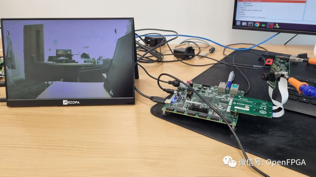
测试
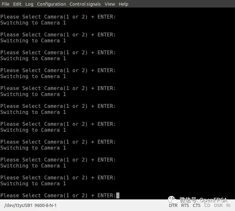
我们可以在连接到 HDMI 输出时运行应用程序并在显示器上看到图像。
使用应用程序选择图像。


总结
项目展示了一个MIPI摄像头接入FPGA的简单、快捷的方式,同时可以学习一下软件的导入工程的方式,简单的基于MicroBlaze系统要学会自己写控制代码,也许这就是新一代“FPGA打工人”需要掌握的一项新技术吧~(doge~不是)
示例工程