Linux 嵌入式设计中最基本的任务之一是创建用户应用程序。
在本篇博文中,我们将探讨如何在 Vitis™ 中使用 UIO 驱动框架创建简单的 Linux 用户应用。
1. 硬件设计
本次使用的是 Zynq UltraScale+ MPSoC ZCU104 评估板。但是,无论您使用任何器件,下列步骤都应适用。
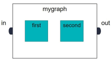
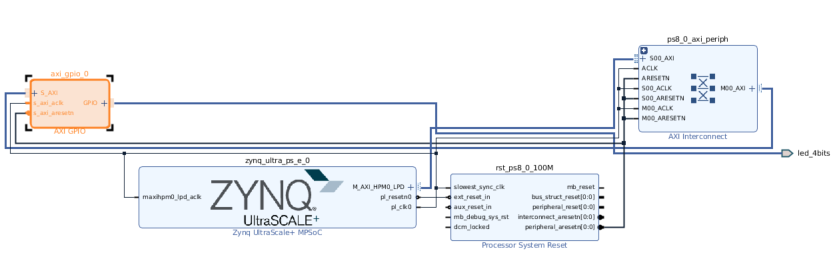
先使用 Vivado® 来创建了块设计。建立了 Zynq UltraScale PS,并把 AXI GPIO 连接到 ZCU104 评估板上的 4 个 LED。
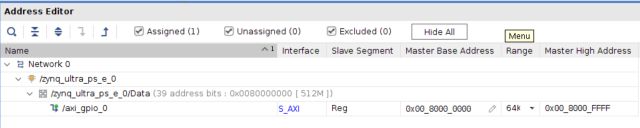
地址映射如下所示:
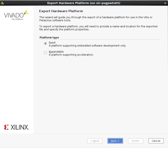
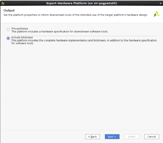
首先 在创建 XSA 时使用了以下选项:
2. Linux 镜像
如果您使用开发板,则建议使用 BSP(如果存在)。
但在本示例中,我们使用模板来创建镜像。已经添加了 UIO 驱动程序,用于 AXI GPIO。
然后创建了 sysroot,在 Vitis 中需要使用它来进行交叉编译。
petalinux-create -t project --template zynqMP -n zcu104_linux

cd zcu104_linux

petalinux-config --get-hw-description=<path to xsa>
依次选择“DTG Settings -> (zcu104-revc)MACHINE_NAME”
petalinux-config -c kernel
Select Device Drivers -> Userspace I/O drivers
<*> Userspace I/O platform driver with generic IRQ handing
<*> Userspace platform driver with generic irq and dynamic memory
将 system-user.dtsi 替换为:
/include/ "system-conf.dtsi"

/ {

    chosen {

        bootargs = "earlycon clk_ignore_unused   uio_pdrv_genirq.of_id=generic-uio";

        stdout-path = "serial0:115200n8";

    };

};


&axi_gpio_0 {

    compatible = "generic-uio";

};
然后,运行以下命令:
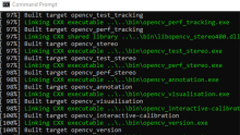
petalinux-build

cd images/linux
petalinux-build --sdk
petalinux-package --sysroot
3. 创建平台
这并非必要步骤,因为用户只需在 Vitis 中使用 sysroot 即可。
但为了便于使用,我们可以创建一个平台并在 Vitis 中使用此平台来创建 Linux 应用。
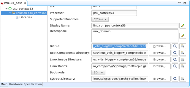
首先,设置平台文件。
把平台文件组织为一种文件夹结构。这并非必要步骤,但用户需要注意 BIF 中的文件路径。
在 Bootgen 中使用 BIF 来创建可启动的镜像。此处我们仅使用占位符文件名。
mkdir -p sw_comp/src/a53/xrt/image
mkdir sw_comp/src/boot
创建 BIF:
the_ROM_image:

{

  [fsbl_config] a53_x64

  [bootloader] <zcu104_base/boot/fsbl.elf>

  [pmufw_image] <zcu104_base/boot/pmufw.elf>

  [destination_device=pl] <system.bit>

  [destination_cpu=a53-0, exception_level=el-3, trustzone] <zcu104_base/boot/bl31.elf>

  [destination_cpu=a53-0, exception_level=el-2] <zcu104_base/boot/u-boot.elf>

}
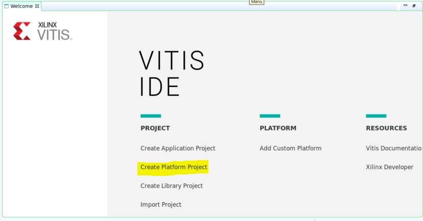
将 linux.bif 复制到sw_comp/src/boot。现在,在 Vitis 中创建一个新平台工程,如下所示:
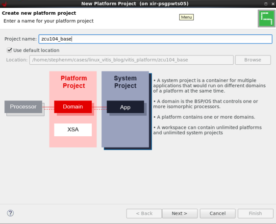
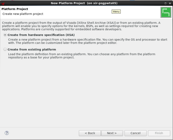
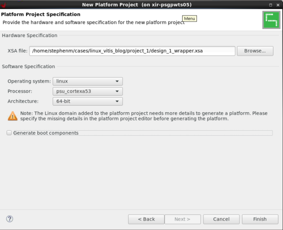
这样就会在zcu104_base/export中创建平台。
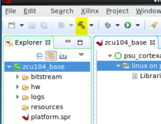
4. 在 Vitis 中创建 Linux 镜像
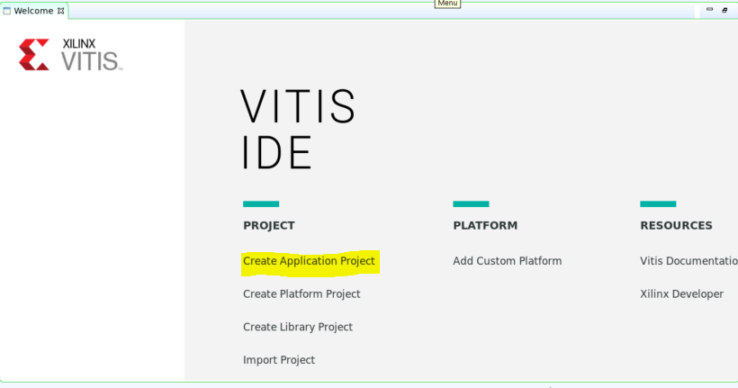
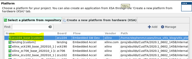
选择“从存储库中选择平台 (Select a platform from therepository)”,单击 + 图标并浏览至您的平台。

创建新应用:

此处可以看到,“应用设置 (Application settings)”默认使用的是平台中的设置。
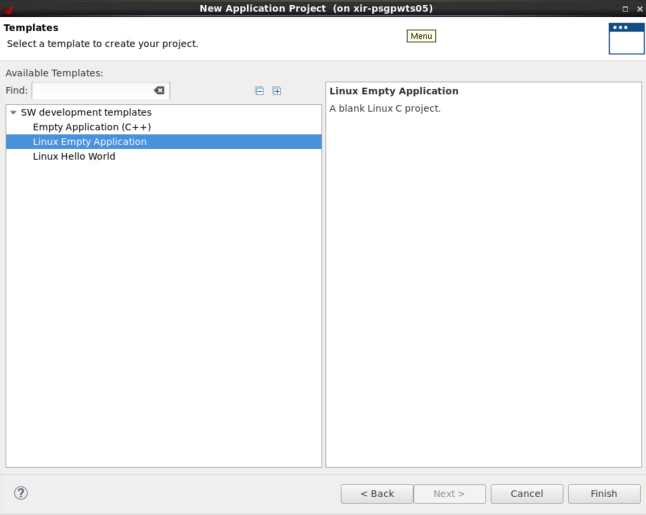
选择“空白应用 (Empty Application)”模板,因为我们将创建自己的自定义应用。
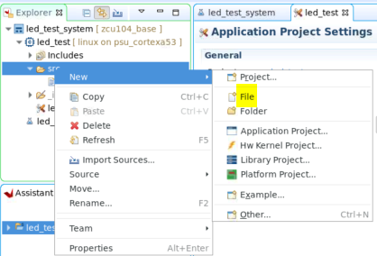
右键单击 led_test 应用下的 src 文件夹,然后选择“新建 (New)”->“文件 (File)”
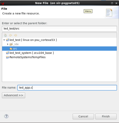
指定其文件名 (.c),然后单击“完成 (Finish)”。
现在,即可将以下代码复制到其中。这是一个简单的 UIO 示例,可用于开关 LED。
#include <stdio.h>

#include <stdlib.h>

#include <unistd.h>

#include <sys/mman.h>

#include <fcntl.h>

#define GPIO_MAP_SIZE           0x10000

#define GPIO_DATA               0x00

#define GPIO_TRI                0x04

#define LED_NUM             256


#define LED_DELAY             10000000


int main(int argc, char *argv[])

{

    int fd;

    char *uiod = "/dev/uio0";

    void *gpio_ptr;

    volatile int Delay;


    printf("AXI GPIO UIO test.\n");


    // open the UIO device file to allow access to the device in user space


    fd = open(uiod, O_RDWR);

    if (fd < 1) {

        printf("Invalid UIO device file:%s.\n", uiod);

        return -1;

    }


    // mmap the GPIO device into user space


    gpio_ptr = mmap(NULL, 4096, PROT_READ|PROT_WRITE, MAP_SHARED, fd, 0);

    if (gpio_ptr == MAP_FAILED) {

        printf("Mmap call failure.\n");

        return -1;

    }


    // set bit0 on the GPIO to be output

    // see pg144 for ref


    *((volatile unsigned *)(gpio_ptr + GPIO_TRI)) = 0x0;


    // Toggle the LED

    while (1) {

        int i;

        unsigned char led_pin = 0x0;

        for (i = 0; i < LED_NUM; i++) {

            *((volatile unsigned *)(gpio_ptr + GPIO_DATA)) = led_pin;

            for (Delay = 0; Delay < LED_DELAY; Delay++);

            *((volatile unsigned *)(gpio_ptr + GPIO_DATA)) = 0x0;

            led_pin++;

        }

    }


    // unmap the GPIO device from user space


    munmap(gpio_ptr, 4096);

    return 0;

}
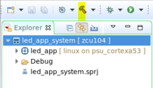
选择系统工程,然后单击锤子图标。这样即可构建可执行文件,并创建启动镜像。
5. 在硬件上执行测试
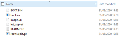
将所有镜像从led_app_system\Debug\sd_card复制到 SD 卡上。
启动后,将自动装载 SD 卡。
在此处更改目录,并执行led_app.elf,如下所示:
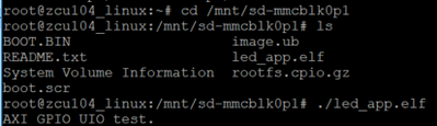
同时,您在板上应该还可以看到 LED 闪烁。
使用 Ctrl + c 即可取消。
本文转载自: Xilinx技术社区微信公众号