作者:小青菜哥哥
原文链接:https://mp.weixin.qq.com/s?__biz=MzUxMTcyNDQyMQ==&mid=2247484492&idx=1&s...
声明:本文由原创博主授权转发,如需转载请联系博主
上篇介绍了JESD204IP核的端口,本篇具体介绍使用该核时所需的全部寄存器,本篇同样比较枯燥,但JESD204IP核的寄存器读写却在实际使用时非常重要,本人在开发过程中来来回回折腾寄存器好多次,就是由于没有正确的理解并配置它,浪费了许多宝贵的时间。
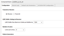
用户需要通过AXI4-lite接口协议来控制JESD204 IP核内部的寄存器空间,正确配置IP核的工作参数,以及在调试过程中读某些状态寄存器的参数,以便确定IP核的工作状态。除特殊情况外,RX和TX核均共享同一段寄存器存储空间。
Xilinx推荐:“当用户通过AXI4-lite接口改变了IP核的配置参数,需要重新将IP核复位,以确保链路按照新的配置参数同步工作。”
如下表所示为IP核的寄存器空间地址和功能描述,地址从0x000~0x9FC,以4为最小步长。
| Table 2-14:Register Address map | ||||
| RX core registers | TX core registers | |||
| 寄存器地址 | 描述 | 读/写 | 描述 | 读/写 |
| 0x000 | Version | 读 | Version | 读 |
| 0x004 | Reset | 读/写 | Reset | 读/写 |
| 0x008 | ILA Support | 读/写 | ILA Support | 读/写 |
| 0x00C | Scrambling | 读/写 | Scrambling | 读/写 |
| 0x010 | SYSREF Handling | 读/写 | SYSREF Handling | 读/写 |
| 0x014 | - | - | ILA Multiframes | 读/写 |
| 0x018 | Test Modes | 读/写 | Test Modes | 读/写 |
| 0x01C | Link Error Status (Lanes 0 to 7) | - | - | - |
| 0x020 | Octets per Frame | 读/写 | Octets per Frame | 读/写 |
| 0x024 | Frames per Multiframe | 读/写 | Frames per Multiframe | 读/写 |
| 0x028 | Lanes in Use | 读/写 | Lanes in Use | 读/写 |
| 0x02C | Subclass Mode | 读/写 | Subclass Mode | 读/写 |
| 0x030 | RX Buffer Delay (RX Only) | 读/写 | - | - |
| 0x034 | Error Reporting (RX Only) | 读/写 | - | - |
| 0x038 | Sync Status | 读 | Sync Status | 读 |
| 0x03C | Debug Status | 读 | - | - |
| 0x040~0x07FC | Reserved | - | Reserved | - |
| 0x400 | Reserved | 读/写 | Lane ID Lane0 | 读/写 |
| 0x404 | Reserved | 读/写 | Lane ID Lane1 | 读/写 |
| 0x408 | Reserved | 读/写 | Lane ID Lane2 | 读/写 |
| 0x40C | Reserved | 读/写 | Lane ID Lane3 | 读/写 |
| 0x410 | Reserved | 读/写 | Lane ID Lane4 | 读/写 |
| 0x414 | Reserved | 读/写 | Lane ID Lane5 | 读/写 |
| 0x418 | Reserved | 读/写 | Lane ID Lane6 | 读/写 |
| 0x41C | Reserved | 读/写 | Lane ID Lane7 | 读/写 |
| 0x800 | lane 0 ILA Config Data 0 | 读 | - | - |
| 0x804 | lane 0 ILA Config Data 1 | 读 | - | - |
| 0x808 | lane 0 ILA Config Data 2 | 读 | - | - |
| 0x80C | lane 0 ILA Config Data 3 | 读 | ILA Config Data 3 | 读/写 |
| 0x810 | lane 0 ILA Config Data 4 | 读 | ILA Config Data 4 | 读/写 |
| 0x814 | lane 0 ILA Config Data 5 | 读 | ILA Config Data 5 | 读/写 |
| 0x818 | lane 0 ILA Config Data 6 | 读 | ILA Config Data 6 | 读/写 |
| 0x81C | lane 0 ILA Config Data 7 | 读 | ILA Config Data 7 | 读/写 |
| 0x820 | lane 0 Test Mode Error Count | 读 | - | - |
| 0x824 | lane 0 Link Error Count | 读 | - | - |
| 0x828 | lane 0 Test Mode ILA Count | 读 | - | - |
| 0x82C | lane 0 Test Mode Multiframe Count | 读 | - | - |
| 0x830 | lane 0 Buffer Adjust | 读 | - | - |
| 0x834~0x83C | lane 0 Reserved | - | - | - |
| 0x840~0x87C | Same as 0x800–0x83C for Lane 1 | 读 | - | - |
| 0x880~0x8BC | Same as 0x800–0x83C for Lane 2 | 读 | - | - |
| 0x8C0–0x8FC | Same as 0x800–0x83C for Lane 3 | 读 | - | - |
| 0x900–0x93C | Same as 0x800–0x83C for Lane 4 | 读 | - | - |
| 0x940–0x97C | Same as 0x800–0x83C for Lane 5 | 读 | - | - |
| 0x980–0x9BC | Same as 0x800–0x83C for Lane 6 | 读 | - | - |
| 0x9C0–0x9FC | Same as 0x800–0x83C for Lane 7 | 读 | - | - |
下面具体介绍各个寄存器的功能:
| Table 2-15: Version(0x000、读) | ||
| Bits | 默认值 | 描述 |
| 31:24 | - | Version固定值1 |
| 23:16 | - | Version固定值2 |
| 15:8 | - | Version固定值3 |
| 7:0 | - | Reserved |
| Table 2-16: Reset(0x004、读/写) | ||
| Bits | 默认值 | 描述 |
| 31:17 | - | Reserved |
| 16 | 1 | Watchdog Timer Disable: 1 = Disable GT watchdog timer。只用于GTXE2收发器 |
| 15:2 | - | Reserved |
| 1 | 0 | Reset (fixed).Write 1 to hold the core in the reset state. Write 0 to release the core from reset. After writing 0 to this bit, Bit 0 of this register should be polled to confirm completion of the reset process.(写0释放复位之后需要用bit0查询复位是否完成) |
| 0 | 1 | Reset (self clearing).Write 1 to reset core .Read: 1 = reset in progress; 0 = reset complete.A reset must be performed as a final step after any changes to the configuration registers. This reset does not clear the configuration register values. It forces a restart and resync of the link using the newly programmed values.(使用) |
| Table 2-17: ILA Support(0x008、读/写) | ||
| Bits | 默认值 | 描述 |
| 31:1 | - | Reserved |
| 0 | 1 | 1 = Enable ILA Support; 0 = Disable ILA Support(初始化链路对齐功能) |
| Table 2-18: Scrambling(0x00C、读/写) | ||
| Bits | 默认值 | 描述 |
| 31:1 | - | Reserved |
| 0 | 0 | 1 = Enable Scrambling; 0 = Disable Scrambling (扰码功能) |
| Table 2-19: SYSREF Handling(0x010、读/写) | ||
| Bits | 默认值 | 描述 |
| 31:17 | - | Reserved |
| 16 | 0 | SYSREF Required on Re-Sync. 1 = a SYSREF event is required following a Link Re-Sync event: TX core transmits K28.5 until a SYSREF re-aligns the LMFC; RX core does not deassert SYNC until a SYSREF event re-aligns the LMFC. 0 = No SYSREF event is required on a Link Re-Sync event: TX core transmits ILA sequence on the next LMFC. RX core deasserts SYNC on the next LMFC.(一般不需要使用) |
| 15:12 | - | Reserved |
| 11:8 | 0000 | SYSREF delay: add additional delay to SYSREF re-alignment of LMFC counter1111 = 15 core_clk cycles delay....0000 = 0 core_clk cycles delay(基本上不需要添加额外的延迟) |
| 7:1 | - | Reserved |
| 0 | 0 | SYSREF Always1 = Core re-aligns LMFC counter on all SYSREF events0 = Core only aligns LMFC counter on the first SYSREF event detected following reset,and ignores subsequent SYSREF events(第一个SYSREF对齐即可) |
| Table 2-20: ILA Multiframes(0x014、读/写,TX) | ||
| Bits | 默认值 | 描述 |
| 31:8 | - | Reserved |
| 7:0 | 0x03 | Multiframes in the Transmitted Initial Lane Alignment SequenceParameter Range: 4–256; program the register with required value minus 1. (默认ILA对齐序列只需4个多帧即可) |
| Table 2-21: Test Modes(0x018、读/写) | ||
| Bits | 默认值 | 描述 |
| 31:5 | - | Reserved |
| 4:0 | 00000 | Test Mode Select00000 = Normal operation00001 = Transmit/Receive /K28.5/ indefinitely00010 = Synchronize as normal then transmit/receive repeated ILA sequences00011 = Transmit/receive /D21.5/ indefinitely [TX Only](2)00101 = Transmit Modified Random Pattern (RPAT) [TX ONLY](2)00111 = Transmit Scrambled Jitter Pattern (JSPAT) [TX ONLY](2)1xxxx = Enable Transceiver’s PRBS test patterns. For correct bit values see relevantTransceiver User Guide (UltraScale) [TX Only](2)10xxx = Enable Transceiver’s PRBS test patterns. For correct bit values see relevantTransceiver User Guide (7-Series) [TX Only](2)See Link Test Modes.(测试模式,测试链路是否正常传输) |
| Table 2-22: Link Error Status (Lanes 0 to 7)(0x01C, 读) | ||
| Bits | 默认值 | 描述(出问题后查看该寄存器值确定问题在哪) |
| 31 | -- | Lane Alignment Error Detected Alarm1 = A Received Multiframe Framing character was detected in a mis-aligned location relative to the LMFC. Alignment error is asserted if any lane sees seven consecutive misaligned alignment characters. |
| 30 | - | SYSREF LMFC Alarm (Subclass 1 Only)1 = A SYSREF event was detected, misaligned to current LMFC counter |
| 29 | - | RX Buffer Overflow Alarm1 = RX Lane Alignment Buffer Overflow has occurred |
| 28:24 | - | Reserved (Read 00000) |
| 23:21 | - | Link Error Status, Lane 7 |
| 20:18 | - | Link Error Status, Lane 6 |
| 17:15 | - | Link Error Status, Lane 5 |
| 14:12 | - | Link Error Status, Lane 4 |
| 11:9 | - | Link Error Status, Lane 3 |
| 8:6 | - | Link Error Status, Lane 2 |
| 5:3 | - | Link Error Status, Lane 1; format as per lane 0 |
| 2:0 | - | Link Error Status, Lane 0bit 2: 1 = Unexpected K-character(s) receivedbit 1: 1 = Disparity Error(s) receivedbit 0: 1 = Not in Table Error(s) receivedEach bit indicates that 1 or more errors of that type have been received in Lane 0 because the register was last read. All status bits are auto-cleared on read of the register. |
| Table 2-23: Octets per Frame(0x020、读/写) | ||
| Bits | 默认值 | 描述(需要配置) |
| 31:8 | - | Reserved |
| 7:0 | 0x01 | Octets per Frame (F). Parameter range 1–256; Program register with required value minus 1(for example, for F = 4, 0x03 should be programmed) |
| Table 2-24: Frames per Multiframe(0x024、读/写) | ||
| Bits | 默认值 | 描述(需要配置) |
| 31:5 | - | Reserved |
| 4:0 | 0x1F | Frames per Multiframe (K). Parameter range 1–32; Program register with required value minus 1(for example, for K = 16, 0x0F should be programmed) |
| Table 2-25: Lanes in Use(0x028、读/写) | ||
| Bits | 默认值 | 描述 |
| 31:12 | - | Reserved |
| 7:0 | Varies depending on Number of Lanes which the core was generated for | Lanes in Use: Allows the number of active lanes to be set. Each bit corresponds to a single lane, when set to “1” lane is active. Lanes 0 to X are active if bits 0 to X are set to 1. For example, for three active lanes (lanes 0 to 2 active), 0x07 is programmed. But if you wanted lane 2 and 0 active, program 0x05. (不用) |
| Table 2-26: Subclass Mode(0x02C、读/写) | ||
| Bits | 默认值 | 描述 |
| 31:3 | - | Reserved |
| 1:0 | 01 | JESD204B 的子类选择,默认子类111: Reserved10: Subclass 201: Subclass 100: Subclass 0 |
| Table 2-27: RX Buffer Delay (RX Only)(0x030、读/写) | ||
| Bits | 默认值 | 描述 |
| 31:10 | - | Reserved |
| 9:0 | 0 | RX Buffer DelayRX Buffer Delay can be programmed, in conjunction with the RX Buffer Adjust values read from the lanes, to minimize the overall RX Latency. See Minimum Deterministic Latency Support.An indication of the maximum allowable reduction of the latency is output on the rx_buffer_adjust register. This provides an indication of the difference between the write and read pointers of the receiver elastic buffer in each lane. The number of octets output in each 10-bit value give an indication of the buffer fill level in each lane. The lowest number given can be programmed to the rx_buffer_delay register to reduce the overall latency by that number of octets.(默认即可) |
| Table 2-28: Error Reporting (RX Only)(0x034、读/写) | ||
| Bits | 默认值 | 描述(默认即可) |
| 31:9 | - | Reserved |
| 8 | 0 | Disable Error Reporting Using SYNC Interface1 = Error reporting using SYNC interface Disabled0 = Error reporting using SYNC interface Enabled |
| 7:1 | 0 | Reserved |
| 0 | 0 | Link Error Counters Enable1 = Enable Link Error counters (Link errors are counted and reported using Link ErrorCount registers per lane)0 = Disable Link Error counters |
| Table 2-29: Sync Status(0x038、读) | ||
| Bits | 默认值 | 描述(调试时需要读该寄存器值,以确定SYSREF和SYNC信号) |
| 31:17 | - | Reserved |
| 16 | 0 | SYSREF Captured (Subclass 1 Only)1 = A SYSREF event has been captured0 = No SYSREF event has been captured |
| 15:1 | 0 | Reserved |
| 0 | 0 | SYNC Status1 = Link SYNC achieved0 = Link SYNC not achieved |
| Table 2-30: Debug Status(0x03C、读) | ||
| Bits | 默认值 | 描述(调试时需要) |
| 31:28 | - | Link Debug status Lane 7 as per lane 0 |
| 27:24 | - | Link Debug status Lane 6 as per lane 0 |
| 23:20 | - | Link Debug status Lane 5 as per lane 0 |
| 19:16 | - | Link Debug status Lane 4 as per lane 0 |
| 15:12 | - | Link Debug status Lane 3 as per lane 0 |
| 11:8 | - | Link Debug status Lane 2 as per lane 0 |
| 7:4 | - | Link Debug status Lane 1 as per lane 0 |
| 3:0 | - | Link Debug status Lane 0Bit 3: 1 = Start of Data was DetectedBit 2: 1 = Start of ILA was DetectedBit 1: 1 = Lane has Code Group SyncBit 0: 1 = Lane is currently receiving K28.5's (BC alignment characters) |
| Table 2-31: Lane ID(0x400~0x41C、读/写、TX 核) | ||
| Bits | 默认值 | 描述(作为TX核使用时对lane编号) |
| 31:5 | - | Reserved |
| 4:0 | N | ID of lane N. Value can be anywhere between 0 and 31. The default value N is set to the lane number. For interfaces using more than 8 lanes and hence multiple JESD204 cores. This register should be programmed to ensure each lane has the correct identifier. |
| Table 2-32: ILA Config Data 0(0x800、读、RX核) | ||
| Bits | 默认值 | 描述(JESD204的版本及子类) |
| 31:11 | - | Reserved |
| 10:8 | - | JESDV (JESD204 version):000=JESD204A 001=JESD204B |
| 7:3 | - | Reserved |
| 2:0 | - | SUBCLASS:000=Subclass0001=Subclass1010=Subclass2 |
| Table 2-33: ILA Config Data 1(0x804、读、RX核) | ||
| Bits | 默认值 | 描述(JESD204的帧字节数F-1) |
| 31:8 | - | Reserved |
| 7:0 | - | F (Octets per Frame). Binary value minus 1. |
| Table 2-34: ILA Config Data 2(0x808、读、RX核) | ||
| Bits | 默认值 | 描述(JESD204的多帧的帧数K-1) |
| 31:5 | - | Reserved |
| 4:0 | - | K (Frames per Multiframe). Binary value minus 1. |
| Table 2-35: ILA Config Data 3(0x80C、读、RX核) | ||
| Bits | 默认值 | 描述(This is a “Per Lane” Register) |
| 31:29 | - | Reserved |
| 28:24 | - | L (Lanes per Link). Binary value minus 1. |
| 23:21 | - | Reserved |
| 20:16 | 0x0 | LID (Lane ID) [RX only, not writeable for TX]. Binary value. |
| 15:12 | - | Reserved |
| 11:8 | 0x 0 | BID (Bank ID). Binary value. |
| 7:0 | 0x 00 | DID (Device ID). Binary value. |
| Table 2-36: ILA Config Data 4(0x810、读、RX核) | ||
| Bits | 默认值 | 描述(This is a “Per Lane” Register) |
| 31:26 | - | Reserved |
| 25:24 | 00 | CS (Control bits per Sample). Binary value. |
| 23:21 | - | Reserved |
| 20:16 | 00000 | N' (Totals bits per Sample). Binary value minus 1. |
| 15:13 | - | Reserved |
| 12:8 | 00000 | N (Convertor Resolution). Binary value minus 1. |
| 7:0 | 0x 00 | M (Convertors per Device). Binary value minus 1. |
| Table 2-37: ILA Config Data 5(0x814、读、RX核) | ||
| Bits | 默认值 | 描述(This is a “Per Lane” Register) |
| 31:29 | - | Reserved |
| 28:24 | 00000 | CF (Control Words per Frame). Binary value. |
| 23:17 | - | Reserved |
| 16 | 0 | HD (High Density format) |
| 15:13 | - | Reserved |
| 12:8 | 00000 | S (Samples per Converter per Frame). Binary value minus 1. |
| 7:1 | - | M (Convertors per Device). Binary value minus 1. |
| 0 | - | SCR (Scrambling Enable) [RX only, not writeable for TX]1 = enabled |
| Table 2-38: ILA Config Data 6(0x818、读、RX核) | ||
| Bits | 默认值 | 描述(This is a “Per Lane” Register) |
| 31:24 | - | Reserved |
| 23:16 | 0x00 | FCHK (Checksum) [RX only, not writeable for TX]. Binary value. |
| 15:8 | 0x00 | RES2 (Reserved Field 2) |
| 7:0 | 0x00 | RES1 (Reserved Field 1) |
| Table 2-39: ILA Config Data 7(0x81C、读、RX核) | ||
| Bits | 默认值 | 描述(This is a “Per Lane” Register) |
| 31:17 | - | Reserved |
| 16 | 0 | ADJDIR (Adjust Direction) [Subclass 2 Only]. Binary value. |
| 15:9 | - | Reserved |
| 8 | 0 | PHADJ (Phase Adjust Request) [Subclass 2 Only]. Binary value. |
| 7:4 | - | Reserved |
| 3:0 | 0x0 | ADJCNT (Phase Adjust Request) [Subclass 2 Only]. Binary value.RX: captured configuration data from the ILA sequence (per lane).TX: Sets the values to be transmitted in the ILA sequence for all lanes. |
| Table 2-40: Test Mode Error Count(0x820、读、RX核) | ||
| Bits | 默认值 | 描述(This is a “Per Lane” Register) |
| 31:0 | - | Test Mode Error CountCount of Errors received in Data link Layer test modes. Test Mode = 001 (Continuous K28.5): counts any non K28.5 characters received. Test Mode = 010 (Continuous ILA): counts any unexpected characters received. This count resets to zero on transition to an active test mode and retains any count value on transition out of an active test mode. |
| Table 2-41: Link Error Count(0x824、读、RX核) | ||
| Bits | 默认值 | 描述(This is a “Per Lane” Register) |
| 31:0 | - | Link Error CountCount of total received link errors (per lane) when Link Error Counters is Enabled. Errors counted are Disparity or Not In Table errors indicated by the lane. The error counter can be reset by disabling and re-enabling using the control bit in the Error Reporting register. |
| Table 2-42: Test Mode ILA Count(0x828、读、RX核) | ||
| Bits | 默认值 | 描述(This is a “Per Lane” Register) |
| 31:0 | - | Test Mode ILA CountCount of total ILA Sequences received when Test Mode = 010 (Continuous ILA). This count resets to zero on transition to Test Mode = 010, and retains any count value on transition out of test mode. |
| Table 2-43: Test Mode Multiframe Count(0x82C、读、RX核) | ||
| Bits | 默认值 | 描述(This is a “Per Lane” Register) |
| 31:0 | - | Test Mode Multiframe CountCount of total ILA Multiframes received when Test Mode = 010 (Continuous ILA) This count resets to zero on transition to Test Mode = 010 and retains any count value on transition out of test mode. |
| Table 2-44: Buffer Adjust(0x830、读、RX核) | ||
| Bits | 默认值 | 描述(This is a “Per Lane” Register) |
| 31:10 | - | Reserved |
| 9:0 | - | RX Buffer Adjust. Indicates the RX Buffer fill level (per lane).This can be used to minimize overall latency. See Minimum Deterministic Latency Support. |
本篇参考JESD204B IP核数据手册,将所有的寄存器列出来了,对于用户来说,其实很多寄存器都不需要配置,保持默认即可,只有少数几个寄存器参数需要用户根据ADC或DAC的工作参数来匹配,另外还有很多寄存器是只读寄存器,里面存储的都是JESD204B的工作状态,当数据传输出现问题时,读取这些参数可以用来快速定位问题所在。