本文转载自:孤独的单刀的CSDN博客
1、带AXIS接口的自定义IP
Vivado在打包IP核的时候提供了AXI4-Stream的接口,接下来分别例化两个IP,一个MASTER,一个SLAVE。将两个接口直接相连,观察Vivado提供的例程,来观察AXI4-Stream的具体实现过程。
手把手教你打包一个自己的Vivado IP核https://blog.csdn.net/wuzhikaidetb/article/details/121216823?spm=1001.20...
https://blog.csdn.net/wuzhikaidetb/article/details/121216823?spm=1001.2014.3001.5501
2、调用IP
2.1、AXI4-Stream MASTER
首先新建一个工程,然后点击Tools-----create and package new ip
点击Next

选择选项4,点击Next,各选项含义:
1---将当前工程打包为IP核
2----将当前工程的模块设计打包为IP核
3----将一个特定的文件夹目录打包为IP核
4----创建一个带AXI接口的IP核

填写IP信息(基本不修改,只把名称改为myip_master方便后面区分)

选择Stream接口,接口类型选择主机Master,数据位宽32位

直接将IP添加到仓库里,IP打包完成

点击IP Catalog ,搜索刚刚打包的IP并将其添加到我们的工程里

参数保持默认,修改一下名字方便管理

点击Generate生成IP

此时在source框中已经生成了IP,下图中文件myip_master_v1_0_M00_AXIS即为底层逻辑文件(后文简单称为发送文件或主机文件)

2.2、AXI4-Stream SLAVE
依照上述步骤再封装一个Slave接口的IP----myip_slave,在将其例化添加到工程,如下(省略打包过程),下图第二个红色方框即为从机的底层文件myip_slave_v1_0_S00_AXIS(后文简单称为接收文件或从机文件)

3、代码解析
个人看法,作为一个FPGA工程师需要具备的两点必备能力:1、优秀的英文资料阅读能力----大多数资料都是英文原文的,鲜有中文版本,即便有,也是别人的二次创作,难免失了些“味道”;此外XILINX的各种手册也是确实写的很好;2、阅读并理解他人优秀代码的能力----站在巨人的肩膀上总是能看得更远,恰好XILINX的工程师们就是这样的巨人。此外,多多阅读优秀代码能拓宽自己的视野,避免闭门造车,有效地提高自己的Coding能力。
所以,接下来,我们将阅读这两个IP的底层文件,来学习AXI-Streaming的使用方式。
3.1、从机接收模块
从机模块的完整代码如下:
`timescale 1 ns / 1 ps

module myip_slave_v1_0_S00_AXIS #
(
// Users to add parameters here

// User parameters ends
// Do not modify the parameters beyond this line

// AXI4Stream sink: Data Width
parameter integer C_S_AXIS_TDATA_WIDTH= 32
)
(
// Users to add ports here

// User ports ends
// Do not modify the ports beyond this line

// AXI4Stream sink: Clock
input wire  S_AXIS_ACLK,
// AXI4Stream sink: Reset
input wire  S_AXIS_ARESETN,
// Ready to accept data in
output wire  S_AXIS_TREADY,
// Data in
input wire [C_S_AXIS_TDATA_WIDTH-1 : 0] S_AXIS_TDATA,
// Byte qualifier
input wire [(C_S_AXIS_TDATA_WIDTH/8)-1 : 0] S_AXIS_TSTRB,
// Indicates boundary of last packet
input wire  S_AXIS_TLAST,
// Data is in valid
input wire  S_AXIS_TVALID
);
// function called clogb2 that returns an integer which has the
// value of the ceiling of the log base 2.
function integer clogb2 (input integer bit_depth);
  begin
    for(clogb2=0; bit_depth>0; clogb2=clogb2+1)
      bit_depth = bit_depth >> 1;
  end
endfunction

// Total number of input data.
localparam NUMBER_OF_INPUT_WORDS  = 8;
// bit_num gives the minimum number of bits needed to address 'NUMBER_OF_INPUT_WORDS' size of FIFO.
localparam bit_num  = clogb2(NUMBER_OF_INPUT_WORDS-1);
// Define the states of state machine
// The control state machine oversees the writing of input streaming data to the FIFO,
// and outputs the streaming data from the FIFO
parameter [1:0] IDLE = 1'b0,        // This is the initial/idle state
                WRITE_FIFO  = 1'b1; // In this state FIFO is written with the
                                    // input stream data S_AXIS_TDATA
wire  axis_tready;
// State variable
reg mst_exec_state;
// FIFO implementation signals
genvar byte_index;
// FIFO write enable
wire fifo_wren;
// FIFO full flag
reg fifo_full_flag;
// FIFO write pointer
reg [bit_num-1:0] write_pointer;
// sink has accepted all the streaming data and stored in FIFO
  reg writes_done;
// I/O Connections assignments

assign S_AXIS_TREADY= axis_tready;
// Control state machine implementation
always @(posedge S_AXIS_ACLK)
begin
  if (!S_AXIS_ARESETN)
  // Synchronous reset (active low)
    begin
      mst_exec_state <= IDLE;
    end
  else
    case (mst_exec_state)
      IDLE:
        // The sink starts accepting tdata when
        // there tvalid is asserted to mark the
        // presence of valid streaming data
          if (S_AXIS_TVALID)
            begin
              mst_exec_state <= WRITE_FIFO;
            end
          else
            begin
              mst_exec_state <= IDLE;
            end
      WRITE_FIFO:
        // When the sink has accepted all the streaming input data,
        // the interface swiches functionality to a streaming master
        if (writes_done)
          begin
            mst_exec_state <= IDLE;
          end
        else
          begin
            // The sink accepts and stores tdata
            // into FIFO
            mst_exec_state <= WRITE_FIFO;
          end

    endcase
end
// AXI Streaming Sink
//
// The example design sink is always ready to accept the S_AXIS_TDATA  until
// the FIFO is not filled with NUMBER_OF_INPUT_WORDS number of input words.
assign axis_tready = ((mst_exec_state == WRITE_FIFO) && (write_pointer <= NUMBER_OF_INPUT_WORDS-1));

always@(posedge S_AXIS_ACLK)
begin
  if(!S_AXIS_ARESETN)
    begin
      write_pointer <= 0;
      writes_done <= 1'b0;
    end
  else
    if (write_pointer <= NUMBER_OF_INPUT_WORDS-1)
      begin
        if (fifo_wren)
          begin
            // write pointer is incremented after every write to the FIFO
            // when FIFO write signal is enabled.
            write_pointer <= write_pointer + 1;
            writes_done <= 1'b0;
          end
          if ((write_pointer == NUMBER_OF_INPUT_WORDS-1)|| S_AXIS_TLAST)
            begin
              // reads_done is asserted when NUMBER_OF_INPUT_WORDS numbers of streaming data
              // has been written to the FIFO which is also marked by S_AXIS_TLAST(kept for optional usage).
              writes_done <= 1'b1;
            end
      end
end
// FIFO write enable generation
assign fifo_wren = S_AXIS_TVALID && axis_tready;
// FIFO Implementation
generate
  for(byte_index=0; byte_index<= (C_S_AXIS_TDATA_WIDTH/8-1); byte_index=byte_index+1)
  begin:FIFO_GEN
    reg  [(C_S_AXIS_TDATA_WIDTH/4)-1:0] stream_data_fifo [0 : NUMBER_OF_INPUT_WORDS-1];
    // Streaming input data is stored in FIFO
    always @( posedge S_AXIS_ACLK )
    begin
      if (fifo_wren)// && S_AXIS_TSTRB[byte_index])
        begin
          stream_data_fifo[write_pointer] <= S_AXIS_TDATA[(byte_index*8+7) -: 8];
        end
    end
  end
endgenerate
// Add user logic here
// User logic ends
endmodule
首先来看接口及参数例化:
`timescale 1 ns / 1 ps
    module myip_slave_v1_0_S00_AXIS #
    (
        // Users to add parameters here
        // User parameters ends
        // Do not modify the parameters beyond this line
        // AXI4Stream sink: Data Width
        parameter integer C_S_AXIS_TDATA_WIDTH    = 32
    )
    (
        // Users to add ports here
        // User ports ends
        // Do not modify the ports beyond this line
        // AXI4Stream sink: Clock
        input wire  S_AXIS_ACLK,
        // AXI4Stream sink: Reset
        input wire  S_AXIS_ARESETN,
        // Ready to accept data in
        output wire  S_AXIS_TREADY,
        // Data in
        input wire [C_S_AXIS_TDATA_WIDTH-1 : 0] S_AXIS_TDATA,
        // Byte qualifier
        input wire [(C_S_AXIS_TDATA_WIDTH/8)-1 : 0] S_AXIS_TSTRB,
        // Indicates boundary of last packet
        input wire  S_AXIS_TLAST,
        // Data is in valid
        input wire  S_AXIS_TVALID
    );
参数:
C_S_AXIS_TDATA_WIDTH,为接收数据的位宽,32位,与我们设置的IP一致;
输入:
S_AXIS_ACLK、S_AXIS_ARESETN、S_AXIS_TDATA、S_AXIS_TSTRB、S_AXIS_TLAST、S_AXIS_TVALID
输出:
S_AXIS_TREADY
输入和输出就是标准的AXI4-Stream协议规定的接口,作为从机,只需要输出一个S_AXIS_TREADY给主机表明自己准备好接收数据,其他接口均有主机输入至从机
需要注意的是,下面的这段话是给我们添加自己的参数、接口、逻辑到底层文件中,实现我们的特定需求,我们本文不用。
        // Users to add parameters here
        // User parameters ends
        // Do not modify the parameters beyond this line
接下来看clogb2这个function,这个function实现的功能就是以2为底开对数,目的是求某寄存器的位宽,举例,某寄存器的最大值为15(2‘b1111),则其位宽应为4位。
    // function called clogb2 that returns an integer which has the
    // value of the ceiling of the log base 2.
    function integer clogb2 (input integer bit_depth);
      begin
        for(clogb2=0; bit_depth>0; clogb2=clogb2+1)
          bit_depth = bit_depth >> 1;
      end
    endfunction
参数定义如下:
// Total number of input data.
    localparam NUMBER_OF_INPUT_WORDS  = 8;
    // bit_num gives the minimum number of bits needed to address 'NUMBER_OF_INPUT_WORDS' size of FIFO.
    localparam bit_num  = clogb2(NUMBER_OF_INPUT_WORDS-1);
    // Define the states of state machine
    // The control state machine oversees the writing of input streaming data to the FIFO,
    // and outputs the streaming data from the FIFO
    parameter [1:0] IDLE = 1'b0,        // This is the initial/idle state
                    WRITE_FIFO  = 1'b1; // In this state FIFO is written with the
                                        // input stream data S_AXIS_TDATA
    wire      axis_tready;
    // State variable
    reg mst_exec_state;
    // FIFO implementation signals
    genvar byte_index;
    // FIFO write enable
    wire fifo_wren;
    // FIFO full flag
    reg fifo_full_flag;
    // FIFO write pointer
    reg [bit_num-1:0] write_pointer;
    // sink has accepted all the streaming data and stored in FIFO
    reg writes_done;
    // I/O Connections assignments
NUMBER_OF_INPUT_WORDS是接收的最大个BYTE数
bit_num是NUMBER_OF_INPUT_WORDS 的位宽
IDLE和WRITE_FIFO分别构成了状态机的两个状态。IDLE----初始状态;WRITE_FIFO----写入FIFO状态
axis_tready是从机接收准备信号
mst_exec_state是状态机的状态变量
byte_index是FIFO的实现参数,后面generate了3个FIFO来存储接收到的数据
fifo_wren是FIFO写使能
fifo_full_flag是FIFO满标志,后面没有用到
write_pointer是FIFO写指针,构成了FIFO的写入逻辑
writes_done是写完所有数据的标志信号
第一个模块的代码:
assign S_AXIS_TREADY    = axis_tready;
    // Control state machine implementation
    always @(posedge S_AXIS_ACLK)
    begin
      if (!S_AXIS_ARESETN)
      // Synchronous reset (active low)
        begin
          mst_exec_state <= IDLE;
        end
      else
        case (mst_exec_state)
          IDLE:
            // The sink starts accepting tdata when
            // there tvalid is asserted to mark the
            // presence of valid streaming data
              if (S_AXIS_TVALID)
                begin
                  mst_exec_state <= WRITE_FIFO;
                end
              else
                begin
                  mst_exec_state <= IDLE;
                end
          WRITE_FIFO:
            // When the sink has accepted all the streaming input data,
            // the interface swiches functionality to a streaming master
            if (writes_done)
              begin
                mst_exec_state <= IDLE;
              end
            else
              begin
                // The sink accepts and stores tdata
                // into FIFO
                mst_exec_state <= WRITE_FIFO;
              end
        endcase
    end
assign S_AXIS_TREADY = axis_tready 这行代码将变量 axis_tready的值赋给了接口S_AXIS_TREADY,而在代码中对axis_tready进行赋值,避免了直接对输出接口进行操作
然后always块描述了状态机的跳转:
首先是初始状态IDLE
当状态机接收到主机发送的数据有效信号后跳转到写FIFO状态WRITE_FIFO
当接收的数据全部数据都被写入FIFO后,又跳转回初始状态IDLE
FIFO写入部分的代码:
下面的语句:当状态机处于写入FIFO的状态,且接收到的数据没有超过最大值时一直拉高从机接收准备信号,表示可以一直接收数据
assign axis_tready = ((mst_exec_state == WRITE_FIFO) && (write_pointer <= NUMBER_OF_INPUT_WORDS-1));
下面的always块:
当FIFO没有被写满且写使能有效时,每个时钟周期写指针+1
当FIFO被写满或者主机发送S_AXIS_TLAST(表明这是最后一个传输数据)时,拉高写入完成信号
always@(posedge S_AXIS_ACLK)
    begin
      if(!S_AXIS_ARESETN)
        begin
          write_pointer <= 0;
          writes_done <= 1'b0;
        end
      else
        if (write_pointer <= NUMBER_OF_INPUT_WORDS-1)
          begin
            if (fifo_wren)
              begin
                // write pointer is incremented after every write to the FIFO
                // when FIFO write signal is enabled.
                write_pointer <= write_pointer + 1;
                writes_done <= 1'b0;
              end
              if ((write_pointer == NUMBER_OF_INPUT_WORDS-1)|| S_AXIS_TLAST)
                begin
                  // reads_done is asserted when NUMBER_OF_INPUT_WORDS numbers of streaming data
                  // has been written to the FIFO which is also marked by S_AXIS_TLAST(kept for optional usage).
                  writes_done <= 1'b1;
                end
          end
    end
下面的语句:当TVALID、TREADY同时有效时拉高FIFO的写使能,这就是AXI4-Stream协议的握手完成后的过程。
assign fifo_wren = S_AXIS_TVALID && axis_tready;
下面的generate块:
例化了4个二维数组stream_data_fifo,并结合写使能、写指针来实现FIFO的功能;FIFO的位宽为8位,而数据位宽为32位,所以每个FIFO分别写入接收数据的0-7,8-15,16-23,24-31位(个人认为这样做的目的是为了实现一个数据的拆分,因为数据的表示多以8位表示)
// FIFO Implementation
    generate
      for(byte_index=0; byte_index<= (C_S_AXIS_TDATA_WIDTH/8-1); byte_index=byte_index+1)
      begin:FIFO_GEN
        reg  [(C_S_AXIS_TDATA_WIDTH/4)-1:0] stream_data_fifo [0 : NUMBER_OF_INPUT_WORDS-1];
        // Streaming input data is stored in FIFO
        always @( posedge S_AXIS_ACLK )
        begin
          if (fifo_wren)// && S_AXIS_TSTRB[byte_index])
            begin
              stream_data_fifo[write_pointer] <= S_AXIS_TDATA[(byte_index*8+7) -: 8];
            end
        end
      end
    endgenerate
至此,就可以对接收模块做一个大致的总结了:
使用状态机实现:IDLE:初始状态,等待主机拉高发送有效信号;WRITE_FIFO:将接收到的8个数据拆分写入4个FIFO
握手过程:主机先拉高VALID信号,从机接收到该信号后进入接收过程,拉高TREADY信号,告知主机自己准备好了接收数据。接收到数据后将其写入FIFO,全部数据被写入后,拉低TREADY信号,表明不在接收数据
3.2、主机发送模块
主机模块的完整代码如下:
`timescale 1 ns / 1 ps

module myip_master_v1_0_M00_AXIS #
(
// Users to add parameters here

// User parameters ends
// Do not modify the parameters beyond this line

// Width of S_AXIS address bus. The slave accepts the read and write addresses of width C_M_AXIS_TDATA_WIDTH.
parameter integer C_M_AXIS_TDATA_WIDTH= 32,
// Start count is the number of clock cycles the master will wait before initiating/issuing any transaction.
parameter integer C_M_START_COUNT= 32
)
(
// Users to add ports here

// User ports ends
// Do not modify the ports beyond this line

// Global ports
input wire  M_AXIS_ACLK,
//
input wire  M_AXIS_ARESETN,
// Master Stream Ports. TVALID indicates that the master is driving a valid transfer, A transfer takes place when both TVALID and TREADY are asserted.
output wire  M_AXIS_TVALID,
// TDATA is the primary payload that is used to provide the data that is passing across the interface from the master.
output wire [C_M_AXIS_TDATA_WIDTH-1 : 0] M_AXIS_TDATA,
// TSTRB is the byte qualifier that indicates whether the content of the associated byte of TDATA is processed as a data byte or a position byte.
output wire [(C_M_AXIS_TDATA_WIDTH/8)-1 : 0] M_AXIS_TSTRB,
// TLAST indicates the boundary of a packet.
output wire  M_AXIS_TLAST,
// TREADY indicates that the slave can accept a transfer in the current cycle.
input wire  M_AXIS_TREADY
);
// Total number of output data
localparam NUMBER_OF_OUTPUT_WORDS = 8;

// function called clogb2 that returns an integer which has the
// value of the ceiling of the log base 2.
function integer clogb2 (input integer bit_depth);
  begin
    for(clogb2=0; bit_depth>0; clogb2=clogb2+1)
      bit_depth = bit_depth >> 1;
  end
endfunction

// WAIT_COUNT_BITS is the width of the wait counter.
localparam integer WAIT_COUNT_BITS = clogb2(C_M_START_COUNT-1);

// bit_num gives the minimum number of bits needed to address 'depth' size of FIFO.
localparam bit_num  = clogb2(NUMBER_OF_OUTPUT_WORDS);

// Define the states of state machine
// The control state machine oversees the writing of input streaming data to the FIFO,
// and outputs the streaming data from the FIFO
parameter [1:0] IDLE = 2'b00,        // This is the initial/idle state

                INIT_COUNTER  = 2'b01, // This state initializes the counter, once
                                // the counter reaches C_M_START_COUNT count,
                                // the state machine changes state to SEND_STREAM
                SEND_STREAM   = 2'b10; // In this state the
                                     // stream data is output through M_AXIS_TDATA
// State variable
reg [1:0] mst_exec_state;
// Example design FIFO read pointer
reg [bit_num-1:0] read_pointer;
// AXI Stream internal signals
//wait counter. The master waits for the user defined number of clock cycles before initiating a transfer.
reg [WAIT_COUNT_BITS-1 : 0] count;
//streaming data valid
wire  axis_tvalid;
//streaming data valid delayed by one clock cycle
reg  axis_tvalid_delay;
//Last of the streaming data
wire  axis_tlast;
//Last of the streaming data delayed by one clock cycle
reg  axis_tlast_delay;
//FIFO implementation signals
reg [C_M_AXIS_TDATA_WIDTH-1 : 0] stream_data_out;
wire  tx_en;
//The master has issued all the streaming data stored in FIFO
reg  tx_done;
// I/O Connections assignments
assign M_AXIS_TVALID = axis_tvalid_delay;
assign M_AXIS_TDATA = stream_data_out;
assign M_AXIS_TLAST = axis_tlast_delay;
assign M_AXIS_TSTRB = {(C_M_AXIS_TDATA_WIDTH/8){1'b1}};

// Control state machine implementation
always @(posedge M_AXIS_ACLK)
begin
  if (!M_AXIS_ARESETN)
  // Synchronous reset (active low)
    begin
      mst_exec_state <= IDLE;
      count    <= 0;
    end
  else
    case (mst_exec_state)
      IDLE:
        // The slave starts accepting tdata when
        // there tvalid is asserted to mark the
        // presence of valid streaming data
        //if ( count == 0 )
        //  begin
            mst_exec_state  <= INIT_COUNTER;
        //  end
        //else
        //  begin
        //    mst_exec_state  <= IDLE;
        //  end

      INIT_COUNTER:
        // The slave starts accepting tdata when
        // there tvalid is asserted to mark the
        // presence of valid streaming data
        if ( count == C_M_START_COUNT - 1 )
          begin
            mst_exec_state  <= SEND_STREAM;
          end
        else
          begin
            count <= count + 1;
            mst_exec_state  <= INIT_COUNTER;
          end

      SEND_STREAM:
        // The example design streaming master functionality starts
        // when the master drives output tdata from the FIFO and the slave
        // has finished storing the S_AXIS_TDATA
        if (tx_done)
          begin
            mst_exec_state <= IDLE;
          end
        else
          begin
            mst_exec_state <= SEND_STREAM;
          end
    endcase
end

//tvalid generation
//axis_tvalid is asserted when the control state machine's state is SEND_STREAM and
//number of output streaming data is less than the NUMBER_OF_OUTPUT_WORDS.
assign axis_tvalid = ((mst_exec_state == SEND_STREAM) && (read_pointer < NUMBER_OF_OUTPUT_WORDS));

// AXI tlast generation
// axis_tlast is asserted number of output streaming data is NUMBER_OF_OUTPUT_WORDS-1
// (0 to NUMBER_OF_OUTPUT_WORDS-1)
assign axis_tlast = (read_pointer == NUMBER_OF_OUTPUT_WORDS-1);


// Delay the axis_tvalid and axis_tlast signal by one clock cycle
// to match the latency of M_AXIS_TDATA
always @(posedge M_AXIS_ACLK)
begin
  if (!M_AXIS_ARESETN)
    begin
      axis_tvalid_delay <= 1'b0;
      axis_tlast_delay <= 1'b0;
    end
  else
    begin
      axis_tvalid_delay <= axis_tvalid;
      axis_tlast_delay <= axis_tlast;
    end
end
//read_pointer pointer
always@(posedge M_AXIS_ACLK)
begin
  if(!M_AXIS_ARESETN)
    begin
      read_pointer <= 0;
      tx_done <= 1'b0;
    end
  else
    if (read_pointer <= NUMBER_OF_OUTPUT_WORDS-1)
      begin
        if (tx_en)
          // read pointer is incremented after every read from the FIFO
          // when FIFO read signal is enabled.
          begin
            read_pointer <= read_pointer + 1;
            tx_done <= 1'b0;
          end
      end
    else if (read_pointer == NUMBER_OF_OUTPUT_WORDS)
      begin
        // tx_done is asserted when NUMBER_OF_OUTPUT_WORDS numbers of streaming data
        // has been out.
        tx_done <= 1'b1;
      end
end

//FIFO read enable generation

assign tx_en = M_AXIS_TREADY && axis_tvalid;

    // Streaming output data is read from FIFO
    always @( posedge M_AXIS_ACLK )
    begin
      if(!M_AXIS_ARESETN)
        begin
          stream_data_out <= 1;
        end
      else if (tx_en)// && M_AXIS_TSTRB[byte_index]
        begin
          stream_data_out <= read_pointer + 32'b1;
        end
    end
// Add user logic here
// User logic ends
endmodule
参数、输入输出端口如下:
module myip_master_v1_0_M00_AXIS #
    (
        // Users to add parameters here
        // User parameters ends
        // Do not modify the parameters beyond this line
        // Width of S_AXIS address bus. The slave accepts the read and write addresses of width C_M_AXIS_TDATA_WIDTH.
        parameter integer C_M_AXIS_TDATA_WIDTH    = 32,
        // Start count is the number of clock cycles the master will wait before initiating/issuing any transaction.
        parameter integer C_M_START_COUNT    = 32
    )
    (
        // Users to add ports here
        // User ports ends
        // Do not modify the ports beyond this line
        // Global ports
        input wire  M_AXIS_ACLK,
        //
        input wire  M_AXIS_ARESETN,
        // Master Stream Ports. TVALID indicates that the master is driving a valid transfer, A transfer takes place when both TVALID and TREADY are asserted.
        output wire  M_AXIS_TVALID,
        // TDATA is the primary payload that is used to provide the data that is passing across the interface from the master.
        output wire [C_M_AXIS_TDATA_WIDTH-1 : 0] M_AXIS_TDATA,
        // TSTRB is the byte qualifier that indicates whether the content of the associated byte of TDATA is processed as a data byte or a position byte.
        output wire [(C_M_AXIS_TDATA_WIDTH/8)-1 : 0] M_AXIS_TSTRB,
        // TLAST indicates the boundary of a packet.
        output wire  M_AXIS_TLAST,
        // TREADY indicates that the slave can accept a transfer in the current cycle.
        input wire  M_AXIS_TREADY
    );
参数:
C_M_AXIS_TDATA_WIDTH是发送数据的位宽
C_M_START_COUNT是初始化的最大计数时钟(这里上电后先延时了一段时间,模拟等待系统稳定)
输入输出:
基本与从机模块一致,不再赘述。
中间变量如下:
// Total number of output data
    localparam NUMBER_OF_OUTPUT_WORDS = 8;

    // function called clogb2 that returns an integer which has the
    // value of the ceiling of the log base 2.
    function integer clogb2 (input integer bit_depth);
      begin
        for(clogb2=0; bit_depth>0; clogb2=clogb2+1)
          bit_depth = bit_depth >> 1;
      end
    endfunction

    // WAIT_COUNT_BITS is the width of the wait counter.
    localparam integer WAIT_COUNT_BITS = clogb2(C_M_START_COUNT-1);

    // bit_num gives the minimum number of bits needed to address 'depth' size of FIFO.
    localparam bit_num  = clogb2(NUMBER_OF_OUTPUT_WORDS);

    // Define the states of state machine
    // The control state machine oversees the writing of input streaming data to the FIFO,
    // and outputs the streaming data from the FIFO
    parameter [1:0] IDLE = 2'b00,        // This is the initial/idle state

                    INIT_COUNTER  = 2'b01, // This state initializes the counter, once
                                    // the counter reaches C_M_START_COUNT count,
                                    // the state machine changes state to SEND_STREAM
                    SEND_STREAM   = 2'b10; // In this state the
                                         // stream data is output through M_AXIS_TDATA
    // State variable
    reg [1:0] mst_exec_state;
    // Example design FIFO read pointer
    reg [bit_num-1:0] read_pointer;
    // AXI Stream internal signals
    //wait counter. The master waits for the user defined number of clock cycles before initiating a transfer.
    reg [WAIT_COUNT_BITS-1 : 0]     count;
    //streaming data valid
    wire      axis_tvalid;
    //streaming data valid delayed by one clock cycle
    reg      axis_tvalid_delay;
    //Last of the streaming data
    wire      axis_tlast;
    //Last of the streaming data delayed by one clock cycle
    reg      axis_tlast_delay;
    //FIFO implementation signals
    reg [C_M_AXIS_TDATA_WIDTH-1 : 0]     stream_data_out;
    wire      tx_en;
    //The master has issued all the streaming data stored in FIFO
    reg      tx_done;
NUMBER_OF_OUTPUT_WORDS是发送数据的最大个数
function--clogb2与接收模块一致
WAIT_COUNT_BITS是等待计时寄存器的位宽
bit_num是发送数据寄存器的位宽
状态机(mst_exec_state):
IDLE:初始状态,只保持一个状态就跳转到状态INIT_COUNTER
INIT_COUNTER:初始化等待状态,等待时间满足后跳转到状态SEND_STREAM
SEND_STREAM:发送数据状态
read_pointer是FIFO的读指针(实际上是没有FIFO,或者说将读指针的值直接发送給从机,模拟了读取FIFO)
count是初始化等待计数器
stream_data_out是发送给从机模块的数据
tx_en是发送使能信号
tx_done是发送完成信号
端口赋值如下:在代码中对AXI4-Stream协议的端口进行赋值,避免了直接对输出接口进行操作
assign M_AXIS_TVALID  = axis_tvalid_delay;
    assign M_AXIS_TDATA   = stream_data_out;
    assign M_AXIS_TLAST   = axis_tlast_delay;
    assign M_AXIS_TSTRB   = {(C_M_AXIS_TDATA_WIDTH/8){1'b1}};
状态机部分:
// Control state machine implementation
    always @(posedge M_AXIS_ACLK)
    begin
      if (!M_AXIS_ARESETN)
      // Synchronous reset (active low)
        begin
          mst_exec_state <= IDLE;
          count    <= 0;
        end
      else
        case (mst_exec_state)
          IDLE:
            // The slave starts accepting tdata when
            // there tvalid is asserted to mark the
            // presence of valid streaming data
            //if ( count == 0 )
            //  begin
                mst_exec_state  <= INIT_COUNTER;
            //  end
            //else
            //  begin
            //    mst_exec_state  <= IDLE;
            //  end

          INIT_COUNTER:
            // The slave starts accepting tdata when
            // there tvalid is asserted to mark the
            // presence of valid streaming data
            if ( count == C_M_START_COUNT - 1 )
              begin
                mst_exec_state  <= SEND_STREAM;
              end
            else
              begin
                count <= count + 1;
                mst_exec_state  <= INIT_COUNTER;
              end

          SEND_STREAM:
            // The example design streaming master functionality starts
            // when the master drives output tdata from the FIFO and the slave
            // has finished storing the S_AXIS_TDATA
            if (tx_done)
              begin
                mst_exec_state <= IDLE;
              end
            else
              begin
                mst_exec_state <= SEND_STREAM;
              end
        endcase
    end
状态机(mst_exec_state):
IDLE:初始状态,只保持一个状态就跳转到状态INIT_COUNTER
INIT_COUNTER:初始化等待状态,等待时间满足后跳转到状态SEND_STREAM
SEND_STREAM:发送数据状态,发送完成后跳转到状态IDLE
下面的语句:当状态机处于发送数据状态,且发送未完成时,拉高axis_tvalid信号,表明此时主机发送数据有效
assign axis_tvalid = ((mst_exec_state == SEND_STREAM) && (read_pointer < NUMBER_OF_OUTPUT_WORDS));
下面的语句:表明此时发送的是最后一个数据
assign axis_tlast = (read_pointer == NUMBER_OF_OUTPUT_WORDS-1);
下面的always块:
为了模拟发送的数据是从FIFO中读出来的(落后一个时钟周期),所以将axis_tvalid_delay、axis_tlast_delay都寄存了一拍,使时序能对齐
// Delay the axis_tvalid and axis_tlast signal by one clock cycle
    // to match the latency of M_AXIS_TDATA
    always @(posedge M_AXIS_ACLK)
    begin
      if (!M_AXIS_ARESETN)
        begin
          axis_tvalid_delay <= 1'b0;
          axis_tlast_delay <= 1'b0;
        end
      else
        begin
          axis_tvalid_delay <= axis_tvalid;
          axis_tlast_delay <= axis_tlast;
        end
    end
读指针部分:
每当发送使能信号有效时:若读指针没有指向最后一个数据,则每个时钟周期+1;若指向了最后一个数据则表明发送完成,拉高发送完成信号tx_done
//read_pointer pointer
    always@(posedge M_AXIS_ACLK)
    begin
      if(!M_AXIS_ARESETN)
        begin
          read_pointer <= 0;
          tx_done <= 1'b0;
        end
      else
        if (read_pointer <= NUMBER_OF_OUTPUT_WORDS-1)
          begin
            if (tx_en)
              // read pointer is incremented after every read from the FIFO
              // when FIFO read signal is enabled.
              begin
                read_pointer <= read_pointer + 1;
                tx_done <= 1'b0;
              end
          end
        else if (read_pointer == NUMBER_OF_OUTPUT_WORDS)
          begin
            // tx_done is asserted when NUMBER_OF_OUTPUT_WORDS numbers of streaming data
            // has been out.
            tx_done <= 1'b1;
          end
    end
读FIFO部分:
握手完成后拉高发送使能信号;
初始发送的值为1,发送过程中发送的数据是读指针的值+1(没有真的从FIFO中读取数据,用逻辑模拟)
//FIFO read enable generation
    assign tx_en = M_AXIS_TREADY && axis_tvalid;           //握手完成后拉高发送使能信号

        // Streaming output data is read from FIFO
        always @( posedge M_AXIS_ACLK )
        begin
          if(!M_AXIS_ARESETN)
            begin
              stream_data_out <= 1;
            end
          else if (tx_en)// && M_AXIS_TSTRB[byte_index]
            begin
              stream_data_out <= read_pointer + 32'b1;
            end
        end
至此,就可以对发送模块做一个大致的总结了:
使用状态机实现:IDLE:初始状态,只保持一个状态就跳转到状态INIT_COUNTER;INIT_COUNTER:初始化等待状态,等待时间满足后跳转到状态SEND_STREAM;SEND_STREAM:发送数据状态,发送完成后跳转到状态IDLE
握手过程:主机先拉高VALID信号,等待从机拉高准备接收信号TREADY,从机拉高TREADY信号,告知主机自己准备好了接收数据。主机开始发送数据,发送全部数据后拉低VALID信号表示数据发送结束
4、仿真及结果
可以看到,发送模块和接收模块的底层逻辑刚刚好可以组合到一起进行仿真验证。将这两个文件在顶层文件分别例化,再编写testbench提供时钟和复位即可。
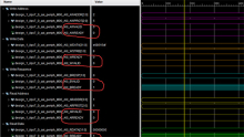
我们使用Modelsim建立工程对其进行仿真,仿真结果如下:
 1. 上电初始过程
2. 延时稳定过程
3. 数据传输过程
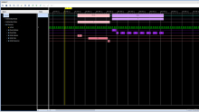
接下来看下发送模块的数据发送过程:

可以很清楚的看到这里的AXI4-Stream协议的握手过程,主机先拉高TVALID,等待从机拉高TREADY后进入发送状态(可以看到这里一共发送了9个数据(1-1-2-3-4-5-6-7-8) ,后面从机定义的FIFO又只接收了8个数据。所以我个人猜测这里应该是有点问题的,可能是想要发送1-8或者0-7这8个数据?)。
接下来看下接收模块的数据接收过程:

握手完成后,从机模块将接收到的数据拆分成4部分(每8bit一个部分,共32bit)写入4个FIFO,由于接收的数据最大值也才7,所以前三个FIFO写入的值均为0。第四个FIFO写入的值与发送模块发送的值一致。
5、其他
一点思考
前面说到,主机发送的模块是发送的9个数据(1-1-2-3-4-5-6-7-8),看起来有一点奇怪。我这里稍微修改一下主机模块AXI_stream_v1_M00_AXIS,代码如下:
`timescale 1 ns / 1 ps

module AXI_stream_v1_M00_AXIS #
(
// Users to add parameters here

// User parameters ends
// Do not modify the parameters beyond this line

// Width of S_AXIS address bus. The slave accepts the read and write addresses of width C_M_AXIS_TDATA_WIDTH.
parameter integer C_M_AXIS_TDATA_WIDTH= 32,
// Start count is the number of clock cycles the master will wait before initiating/issuing any transaction.
parameter integer C_M_START_COUNT= 32
)
(
// Users to add ports here

// User ports ends
// Do not modify the ports beyond this line

// Global ports
input wire  M_AXIS_ACLK,
//
input wire  M_AXIS_ARESETN,
// Master Stream Ports. TVALID indicates that the master is driving a valid transfer, A transfer takes place when both TVALID and TREADY are asserted.
output wire  M_AXIS_TVALID,
// TDATA is the primary payload that is used to provide the data that is passing across the interface from the master.
output wire [C_M_AXIS_TDATA_WIDTH-1 : 0] M_AXIS_TDATA,
// TSTRB is the byte qualifier that indicates whether the content of the associated byte of TDATA is processed as a data byte or a position byte.
output wire [(C_M_AXIS_TDATA_WIDTH/8)-1 : 0] M_AXIS_TSTRB,
// TLAST indicates the boundary of a packet.
output wire  M_AXIS_TLAST,
// TREADY indicates that the slave can accept a transfer in the current cycle.
input wire  M_AXIS_TREADY
);
// Total number of output data
localparam NUMBER_OF_OUTPUT_WORDS = 8;

// function called clogb2 that returns an integer which has the
// value of the ceiling of the log base 2.
function integer clogb2 (input integer bit_depth);
  begin
    for(clogb2=0; bit_depth>0; clogb2=clogb2+1)
      bit_depth = bit_depth >> 1;
  end
endfunction

// WAIT_COUNT_BITS is the width of the wait counter.
localparam integer WAIT_COUNT_BITS = clogb2(C_M_START_COUNT-1);

// bit_num gives the minimum number of bits needed to address 'depth' size of FIFO.
localparam bit_num  = clogb2(NUMBER_OF_OUTPUT_WORDS);

// Define the states of state machine
// The control state machine oversees the writing of input streaming data to the FIFO,
// and outputs the streaming data from the FIFO
parameter [1:0] IDLE = 2'b00,        // This is the initial/idle state

                INIT_COUNTER  = 2'b01, // This state initializes the counter, once
                                // the counter reaches C_M_START_COUNT count,
                                // the state machine changes state to SEND_STREAM
                SEND_STREAM   = 2'b10; // In this state the
                                     // stream data is output through M_AXIS_TDATA
// State variable
reg [1:0] mst_exec_state;
// Example design FIFO read pointer
reg [bit_num-1:0] read_pointer;
// AXI Stream internal signals
//wait counter. The master waits for the user defined number of clock cycles before initiating a transfer.
reg [WAIT_COUNT_BITS-1 : 0] count;
//streaming data valid
wire  axis_tvalid;
//streaming data valid delayed by one clock cycle
reg  axis_tvalid_delay;
//Last of the streaming data
wire  axis_tlast;
//Last of the streaming data delayed by one clock cycle
reg  axis_tlast_delay;
//FIFO implementation signals
reg [C_M_AXIS_TDATA_WIDTH-1 : 0] stream_data_out;
wire  tx_en;
//The master has issued all the streaming data stored in FIFO
reg  tx_done;
// I/O Connections assignments
assign M_AXIS_TVALID = tx_en;
assign M_AXIS_TDATA= stream_data_out;
assign M_AXIS_TLAST= axis_tlast;
assign M_AXIS_TSTRB= {(C_M_AXIS_TDATA_WIDTH/8){1'b1}};


// Control state machine implementation
always @(posedge M_AXIS_ACLK)
begin
  if (!M_AXIS_ARESETN)
  // Synchronous reset (active low)
    begin
      mst_exec_state <= IDLE;
      count    <= 0;
    end
  else
    case (mst_exec_state)
      IDLE:
        // The slave starts accepting tdata when
        // there tvalid is asserted to mark the
        // presence of valid streaming data
        //if ( count == 0 )
        //  begin
            mst_exec_state  <= INIT_COUNTER;
        //  end
        //else
        //  begin
        //    mst_exec_state  <= IDLE;
        //  end

      INIT_COUNTER:
        // The slave starts accepting tdata when
        // there tvalid is asserted to mark the
        // presence of valid streaming data
        if ( count == C_M_START_COUNT - 1 )
          begin
            mst_exec_state  <= SEND_STREAM;
          end
        else
          begin
            count <= count + 1;
            mst_exec_state  <= INIT_COUNTER;
          end

      SEND_STREAM:
        // The example design streaming master functionality starts
        // when the master drives output tdata from the FIFO and the slave
        // has finished storing the S_AXIS_TDATA
        if (tx_done)
          begin
            mst_exec_state <= IDLE;
          end
        else
          begin
            mst_exec_state <= SEND_STREAM;
          end
    endcase
end


//tvalid generation
//axis_tvalid is asserted when the control state machine's state is SEND_STREAM and
//number of output streaming data is less than the NUMBER_OF_OUTPUT_WORDS.
assign axis_tvalid = ((mst_exec_state == SEND_STREAM) && (read_pointer < NUMBER_OF_OUTPUT_WORDS));

// AXI tlast generation
// axis_tlast is asserted number of output streaming data is NUMBER_OF_OUTPUT_WORDS-1
// (0 to NUMBER_OF_OUTPUT_WORDS-1)
assign axis_tlast = (read_pointer == NUMBER_OF_OUTPUT_WORDS-1);


// Delay the axis_tvalid and axis_tlast signal by one clock cycle
// to match the latency of M_AXIS_TDATA
always @(posedge M_AXIS_ACLK)
begin
  if (!M_AXIS_ARESETN)
    begin
      axis_tvalid_delay <= 1'b0;
      axis_tlast_delay <= 1'b0;
    end
  else
    begin
      axis_tvalid_delay <= axis_tvalid;
      axis_tlast_delay <= axis_tlast;
    end
end
//read_pointer pointer
always@(posedge M_AXIS_ACLK)
begin
  if(!M_AXIS_ARESETN)
    begin
      read_pointer <= 0;
      tx_done <= 1'b0;
    end
  else
    if (read_pointer <= NUMBER_OF_OUTPUT_WORDS-1)
      begin
        if (tx_en)
          // read pointer is incremented after every read from the FIFO
          // when FIFO read signal is enabled.
          begin
            read_pointer <= read_pointer + 1;
            tx_done <= 1'b0;
          end
      end
    else if (read_pointer == NUMBER_OF_OUTPUT_WORDS)
      begin
        // tx_done is asserted when NUMBER_OF_OUTPUT_WORDS numbers of streaming data
        // has been out.
        tx_done <= 1'b1;
      end
end


//FIFO read enable generation

assign tx_en = M_AXIS_TREADY && axis_tvalid_delay && axis_tvalid ;

    // Streaming output data is read from FIFO
    always @( posedge M_AXIS_ACLK )
    begin
      if(!M_AXIS_ARESETN)
        begin
stream_data_out <= 0;
        end
      else if (tx_en)// && M_AXIS_TSTRB[byte_index]
        begin
          stream_data_out <= read_pointer + 32'b1;
        end
    end
// Add user logic here
// User logic ends
endmodule
修改testbench分别对发送模块的三种握手模式进行仿真,结果如下:
主机先拉高TVALID,从机后拉高TREADY:发送了0-7共8个数据

从机先拉高TREADY, 主机后拉高TVALID:发送了0-7共8个数据

主机、从机同时分别拉高TVALID,READY:发送了0-7共8个数据

结合从机模块进行的仿真:
主机先拉高TVALID,从机后拉高TREADY:发送了0-7共8个数据。从机模块接收到0-7共8个数据分别拆分写入4个FIFO

后话
接下来详解AXI4-Stream接口的IP核----AXI4-STREAM DATA FIFO。
需要整个工程的朋友可以私信或者评论留下邮箱