作者:Nathan Xu,AMD工程师;来源:AMD开发者社区
Petalinux工程:
1. 设置好2022.2 Petalinux环境. 使用2022.2 ZCU106 BSP, 创建Petalinux工程:
这个例子的BSP_DIR= /proj/petalinux/released/Petalinux v2022.2/finalrelease/release/petalinux-v2022.2_10141622/bsp/release
2. CD到新建的petalinux工程下:
cd xilinx-zcu106-2022.2/
3. 在上面Vivado生成的.xsa文件导入到petalinux工程:
XSA文件在<your directory>/v_multi_scaler_0_ex/.
System Configuration:
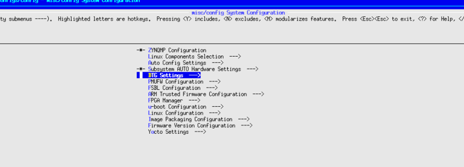
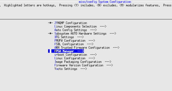
4. 在system configuration配置页面, 选择DTG settings
5. 在DTG settings页面, 按”n”把“Remove PL from device tree”勾掉, 确保这个选项不要选上
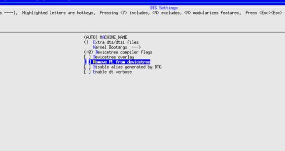
6. 在DTG Settings→kernel Bootargs→Add extra boot args, 可以加上 cma=1700M.
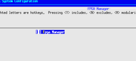
7. 在system configuration配置页面, 选择FPGA manager, 按“n”把FPGA manager选项勾掉.
Kernel configuration:
8. 运行下面命令
Petalinux-config -c kernel
9. 在kernel配置页面, 确保CONFIG_VIDEO_XILINX, CONFIG_VIDEO_DEV, CONFIG_VIDEO_V4L2, CONFIG_VIDEO_XILINX_MULTISCALER这些选项都已经配置好.

10. 可以在kernel配置页面, 用‘/’来搜索这些配置是否已经设置.


Rootfs配置:
11. 运行下面命令, 配置rootfs.
在Filesystem Packages→misc→v4l-utils , 配置好v4l-utils, libv4l, media-ctl.
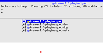
在Filesystem Packages→misc→gstreamer1.0-plugins-good, 按”y”把下面选项都勾上.
编译Petalinux工程:
14. petalinux-build
创建boot image:
15. cd images/linux
16. petalinux-package --boot --fsbl zynqmp_fsbl.elf --u-boot u-boot.elf --pmufw pmufw.elf --fpga system.bit
拷贝image到SD card:
17. 把生成的BOOT.BIN, system.dtb, Image, rootfs.cpio.gz.u-boot, boot.scr 拷贝搭配SD card.
ZCU106板卡设置与连接:
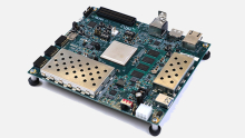
18. Connect the Micro USB cable into the ZCU106 Board Micro USB port J83, and the other end into an open USB port on the host PC. This cable is used for UART over USB communication.
19. Insert the SD card with the images copied into the SD card slot J100.
20. Set the SW6 switches as shown in the below Figure. This configures the boot settings to boot from SD.

21. Connect 12V Power to the ZCU106 6-Pin Molex connector.
22. Set up a terminal session between a PC COM port and the serial port on the evaluation board
Run the image on ZCU106:
23. 在linux booting完成后, 运行下面的gst-launch命令:
24. 把SD card mount到/mnt/
25. 把刚才生成的out_chan0.rgb拷贝到/mnt
在YUV player打开out_chan0.rgb
26. 设置YUV player的size为1080p, color为RGB24, zoom设置为1:2或者1:4. 打开out_chan0.rgb, 就能看到下面图片:

Multi-scaler在linux的debug:
27. 比较常见的问题, 是在运行上面的gst-launch命令, 找不到“v4l2convert” element, 遇到这个错误,需要看multi-scaler在boot log有没有probe到. 一个经常看到的原因, 是multi-scaler的device tree里reset-gpios这个property是必须的, 但DTG有的时候没有产生这个property, 或者是gpio没有连接到multi-scaler的reset管脚, 所以确保reset-gpios这个property在device tree, 否则就会看到错误. 下面是video multi-scaler device tree的参考例子, 如果不确定device tree是否正确, 对比下面的例子, 检查device tree是否有缺少的property.

28. multi-scaler的第一个node, 它的gstreamer element是"v4l2convert" 而不是 "v4l2video0convert", 之前第一个node是v4l2video0convert, 第二个node是v4l2video1convert, 现在 1st node是 "v4l2convert", 2nd 是“v4l2video1convert ”.


